■ Specifications and Test Methods
No Item
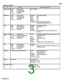
17 Insulation
Specification
Test Method(Ref. Standard:AEC-Q200)
Measurement Temperature
Measurement Voltage
Charging Time
More than 1000MΩ
25℃
Rated Voltage
1min
Resistance(I.R.)
(Room Temperature)
Charge/discharge current 50mA max.
Measurement Temperature
Measurement Voltage
Charging Time
More than 100MΩ
125℃
Rated Voltage
1min
18 Insulation
Resistance(I.R.)
(High Temperature)
Charge/discharge current 50mA max.
No defects or abnormalities.
Test Voltage
Applied Time
Charge/discharge current 50mA max.
250% of the rated voltage
1s to 5s
19 Voltage proof
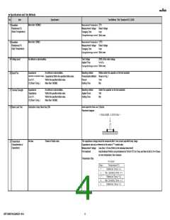
20 Board Flex
Appearance
No defects or abnormalities.
Mounting method
Pressurization Method
Flexure
Reflow solder the capacitor on the test substrate
Shown in Fig.2
1mm
Capacitance or Capacitance Change
Capacitance:Within the specified initial value.
Within the specified initial value.
More than 1000MΩ
Q or D.F.
I.R.(Room Temp.)
Holding Time
60s
Appearance
Capacitance
Q or D.F.
No defects or abnormalities.
Within the specified initial value.
Within the specified initial value.
More than 1000MΩ
Mounting method
Applied Force
Holding Time
Solder the capacitor on the test substrate
18N
60s
21 Terminal Strength
22 Beam Load Test
I.R.(Room Temp.)
Speed supplied the Stress Load
Destruction Value: More than 20N
0.5mm/s
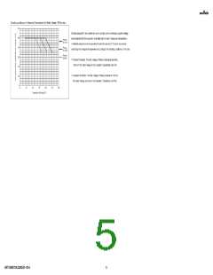
Placement diagram
No bias
Shown in Rated value.
The capacitance change should be measured after 5 min at each specified temp. stage.
Capacitance value as a reference is the value in "*" marked step.
23 Temperature
Characteristics of
Capacitance
Measurement Voltage
Pre-treatment
Less than 1.0Vrms (Refer to the individual data sheet)
Heat treatment:Perform a heat treatment at 150+0/-10°C for 1hour and then let sit for 24+/-2hours
at room temperature, then measure.
Temperature Step
GRT188R72A332KE01-01A
4

 MURATA [ muRata ]