■ Specifications and Test Methods
No Item
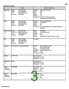
19 Voltage proof
Specification
Test Method(Ref. Standard:AEC-Q200)
250% of the rated voltage
1s to 5s
No defects or abnormalities.
Test Voltage
Applied Time
Charge/discharge current 50mA max.
Appearance
Capacitance or Capacitance Change
No defects or abnormalities.
Capacitance Change:Within +/-5%
Within the specified initial value.
More than 10000MΩ
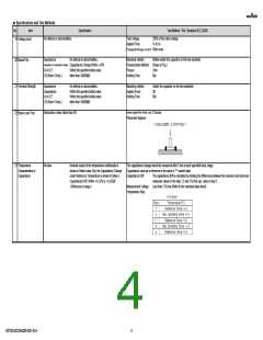
Mounting method
Pressurization Method
Flexure
Reflow solder the capacitor on the test substrate
Shown in Fig.2
2mm
20 Board Flex
Q or D.F.
I.R.(Room Temp.)
Holding Time
60s
Appearance
Capacitance
Q or D.F.
No defects or abnormalities.
Within the specified initial value.
Within the specified initial value.
More than 10000MΩ
Mounting method
Applied Force
Holding Time
Solder the capacitor on the test substrate
2N
60s
21 Terminal Strength
22 Beam Load Test
I.R.(Room Temp.)
Speed supplied the Stress Load
Destruction Value: More than 5N
0.1mm/s
Placement diagram
No bias
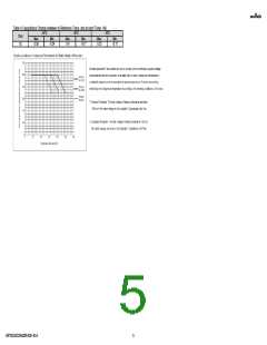
Nominal values of the temperature coefficientis is
The capacitance change should be measured after 5 min at each specified temp. stage.
Capacitance value as a reference is the value in "*" marked step.
23 Temperature
Characteristics of
Capacitance
shown in Rated value. But, the Capacitance Change
under Reference Temperature is shown inTable A.
Capacitance Drift: Within +/-0.2% or +/-0.05pF
(Whichever is larger.)
Capacitance Drift
The capacitance drift is calculated by dividing the differences between the maximum and minimum
measured values in the step 1,3 and 5 by the cap. value in step 3.
Less than 1.0Vrms (Refer to the individual data sheet)
Measurement Voltage
Temperature Step
GRT0335C2A820FA02-01A
4

 MURATA [ muRata ]