• This PDF catalog is downloaded from the website of Murata Manufacturing co., ltd. Therefore, it’s specifications are subject to change or our products in it may be discontinued without advance notice. Please check with our
• Please read rating and !CAUTION (for storage, operating, rating, soldering, mounting and handling) in this catalog to prevent smoking and/or burning, etc.
!Note
!Note
C02E.pdf
sales representatives or product engineers before ordering.
• This catalog has only typical specifications because there is no space for detailed specifications. Therefore, please approve our product specifications or transact the approval sheet for product specifications before ordering0. 9.9.18
• This PDF catalog has only typical specifications because there is no space for detailed specifications. Therefore, please approve our product specifications or transact the approval sheet for product specifications before ordering.
GQM Series Specifications and Test Methods (1)
GQM Series Specifications and Test Methods
Specifications
No.
1
Item
Operating
Test Method
Reference Temperature: 25D
Y55 to 125D
Temperature
The rated voltage is defined as the maximum voltage which
may be applied continuously to the capacitor.
When AC voltage is superimposed on DC voltage, V or V ,
P-P
O-P
2
Rated Voltage
See the previous page.
whichever is larger, should be maintained within the rated
voltage range.
Visual inspection
Using calipers
3
4
Appearance
Dimension
No defects or abnormalities
Within the specified dimensions
No failure should be observed when 300% of the rated voltage
is applied between the terminations for 1 to 5 seconds,
provided the charge/discharge current is less than 50mA.
250V only 250%
5
5
Dielectric Strength No defects or abnormalities
Insulation Resistance More than 10,000MΩ
The insulation resistance should be measured with a DC
voltage not exceeding the rated voltage at 25D and 75%RH
max. and within 2 minutes of charging.
6
7
Capacitance
Q
Within the specified tolerance
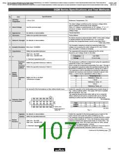
The capacitance/Q should be measured at 25D at the
frequency and voltage shown in the table.
30pF min.: QU1400
30pF max.: QU800W20C
1T0.1MHz
Frequency
Voltage
8
0.5 to 5Vrms
C: Nominal Capacitance (pF)
Capacitance
Change
The temperature coefficient is determined using the capacitance
measured in step 3 as a reference.
Within the specified tolerance (Table A)
When cycling the temperature sequentially from step 1 through 5
the capacitance should be within the specified tolerance for the
temperature coefficient and capacitance change as in Table A.
The capacitance drift is calculated by dividing the differences
between the maximum and minimum measured values in the
steps 1, 3 and 5 by the capacitance value in step 3.
Temperature
Coefficient
Within the specified tolerance (Table A)
Capacitance
Temperature
Characteristics
9
Step
Temperature (D)
Reference Temp. T2
Y55T3
Capacitance
Drift
Within T0.2% or T0.05pF
(Whichever is larger)
1
2
3
4
5
Reference Temp. T2
125T3
Reference Temp. T2
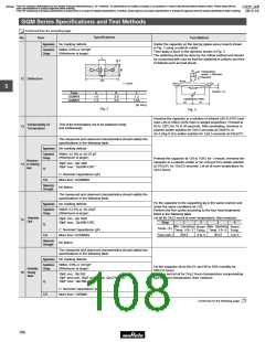
No removal of the terminations or other defect should occur.
Solder the capacitor to the test jig (glass epoxy board) shown in
Fig. 1 using a eutectic solder. Then apply 10N* force in parallel
with the test jig for 10T1 sec.
The soldering should be done either with an iron or using the
reflow method and should be conducted with care so that the
soldering is uniform and free of defects such as heat shock.
*5N (GQM188)
c
Adhesive Strength
of Termination
10
Type
a
b
c
GQM18
GQM21
1.0
1.2
3.0
4.0
1.2
1.65
Solder resist
(in mm)
Baked electrode or
copper foil
Fig. 1
Appearance
Capacitance
No defects or abnormalities
Within the specified tolerance
Solder the capacitor to the test jig (glass epoxy board) in the
same manner and under the same conditions as (10).
The capacitor should be subjected to a simple harmonic motion
having a total amplitude of 1.5mm, the frequency being varied
uniformly between the approximate limits of 10 and 55Hz. The
frequency range, from 10 to 55Hz and return to 10Hz, should
be traversed in approximately 1 minute.
Vibration
Resistance
Q
30pF min.: QU1400
30pF max.: QU800W20C
11
C: Nominal Capacitance (pF)
This motion should be applied for a period of 2 hours in each of
3 mutually perpendicular directions (total of 6 hours).
Continued on the following page.
105

 MURATA [ muRata ]