■ Specifications and Test Methods
No Item
Specification
Test Method(Ref. Standard:JIS C 5101, IEC60384)
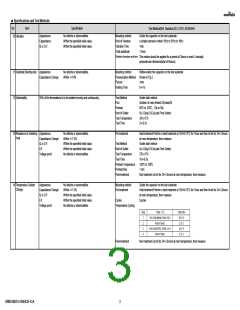
1 Rated Voltage
Shown in Rated value.
The rated voltage is defined as the maximum voltage which may be applied continuously to the capacitor.
When AC voltage is superimposed on DC voltage, V(peak to peak) or V(zero to peak),
whichever is larger, should be maintained within the rated voltage range.
2 Appearance
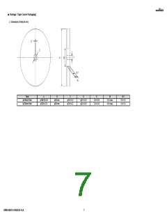
3 Dimension
No defects or abnormalities.
Shown in Dimension.
Visual inspection
Using Measuring instrument of dimension.
4 Voltage proof
No defects or abnormalities.
Measurement Point
Test Voltage
Applied Time
Between the terminations
250% of the rated voltage
1s to 5s
Charge/discharge current 50mA max.
5 Insulation
More than 50Ω・F
Measurement Temperature Room Temperature
Resistance(I.R.)
(Room Temperature)
Measurement Point
Measurement Voltage
Charging Time
Between the terminations
Rated Voltage
1min
Charge/discharge current 50mA max.
6 Capacitance
Shown in Rated value.
Measurement Temperature Room Temperature
Measurement Frequency 1.0+/-0.1kHz
Measurement Voltage
0.5+/-0.1Vrms
Measurement Temperature Room Temperature
Measurement Frequency 1.0+/-0.1kHz
7 Q or Dissipation Factor DF≦0.1
(D.F.)
Measurement Voltage
0.5+/-0.1Vrms
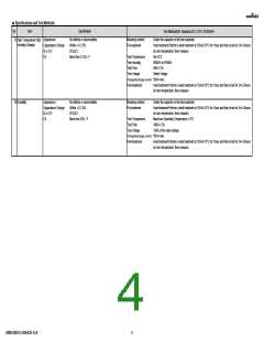
8 Temperature
Characteristics of
Capacitance
No bias
Shown in Rated value.
The capacitance change should be measured after 5 min at each specified temp. stage.
Capacitance value as a reference is the value in "*" marked step.
Measurement Voltage
Pre-treatment
Less than 1.0Vrms (Refer to the individual data sheet)
Heat treatment:Perform a heat treatment at 150+0/-10°C for 1hour and then let sit for 24+/-2hours
at room temperature, then measure.
Temperature Step
9 Adhesive Strength of
Termination
No removal of the terminations or other defect should occur.
Mounting method
Applied Force
Solder the capacitor on the test substrate
5N
Holding Time
10+/-1s
Applied Direction
In parallel with the test substrate and vertical with the capacitor side
GRM185B31A105KE35-01A
2

 MURATA [ muRata ]