• Please read rating and !CAUTION (for storage, operating, rating, soldering, mounting and handling) in this catalog to prevent smoking and/or burning, etc.
• This catalog has only typical specifications because there is no space for detailed specifications. Therefore, please review our product specifications or consult the approval sheet for product specifications before ordering.
!Note
C85E.pdf
Jul.13,2011
Safety Standard Certified Type KJ for Automotive Specifications and Test Methods
Type KJ Specifications and Test Methods
Continued from the preceding page.
No.
Item
Appearance
Specifications
Test Method
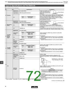
Solder the capacitor and gum
up the body to the test jig
(glass epoxy board) by resin
(adhesive).
No marked defect
Within the specified tolerance
Resin (Adhesive)
Capacitance
The capacitor should be firmly soldered to the supporting lead
wire, 1.5mm in total amplitude, with about a 20 minutes rate of
vibration change from 10Hz to 2000Hz and back to 10Hz.
This motion should be applied 12 times in each of 3 mutually
perpendicular directions (total of 36 times).
10 Vibration
Char.
B, E
Specifications
D.F.V2.5%
D.F.
The acceleration is 5g max.
Appearance
Capacitance
No marked defect
Solder the capacitor and gum
up the body to the test
jig (glass epoxy board) by
Within the specified tolerance
Resin (Adhesive)
resin (adhesive).
Mechanical
Shock
Char.
B, E
Specifications
D.F.V5.0%
11
D.F.
Three shocks in each direction should be applied along 3
mutually perpendicular axes to and from of the test specimen
(18 shocks).
The specified test pulse should be half-sine and should have a
duration: 0.5ms, peak value: 100g and velocity change: 4.7m/s.
I.R.
10000MΩ min.
Appearance
No marked defect
Char.
B
E
Capacitance Change
Within ±10%
Capacitance
Change
Set the capacitor for 1000±12 hrs. at 85±3°C in 80 to 85%
relative humidity.
Within ±15%
Humidity
(Under
Steady
State)
Pre-treatment:
12
Char.
B, E
Specifications
D.F.V5.0%
Capacitor should be stored at 125±3°C for 1hr., then placed
at room condition* for 24±2 hrs. before initial measurements.
Post-treatment:
D.F.
I.R.
3000MΩ min.
Per Item 6
Capacitor should be stored for 1 to 2 hrs. at room condition.*
Dielectric
Strength
Appearance
No marked defect
Apply the rated voltage for 1000±12 hrs. at 85±3°C in 80 to
85% relative humidity.
Char.
B
E
Capacitance Change
Within ±10%
Capacitance
Change
Within ±15%
Humidity
13
Pre-treatment:
Loading
Capacitor should be stored at 125±3°C for 1hr., then placed
at room condition* for 24±2 hrs. before initial measurements.
Post-treatment:
Char.
B, E
Specifications
D.F.V5.0%
D.F.
Capacitor should be stored for 1 to 2 hrs. at room condition.*
I.R.
3000MΩ min.
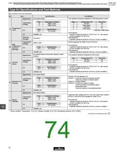
Appearance
No marked defect
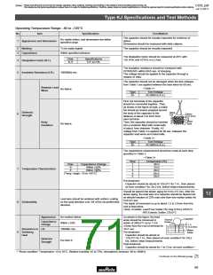
Impulse Voltage
Each individual capacitor should be subjected to a 5kV
impulses for three times. Then the capacitors are applied to life
test.
Capacitance
Change
Within ±20%
3000MΩ min.
I.R.
100 (%)
Front time (T1) =1.2µs=1.67T
90
Time to half-value (T2) =50µs
50
30
0
t
12
T
T
1
14
T
2
Life
Apply a voltage from Table 4 for 1000 hrs. at 125+2/-0°C, and
relative humidity of 50% max.
Dielectric
Strength
Per Item 6
<Table 4>
Applied Voltage
AC510V(r.m.s.), except that once each hour the voltage
is increased to AC1000V(r.m.s.) for 0.1 sec.
Pre-treatment:
Capacitor should be stored at 125±3°C for 1hr., then placed
at room condition* for 24±2 hrs. before initial measurements.
Post-treatment:
Capacitor should be stored for 1 to 2 hrs. at room condition.*
* "Room condition" Temperature: 15 to 35°C, Relative humidity: 45 to 75%, Atmospheric pressure: 86 to 106kPa
Continued on the following page.
70

 MURATA [ muRata ]