APPLICATION NOTES
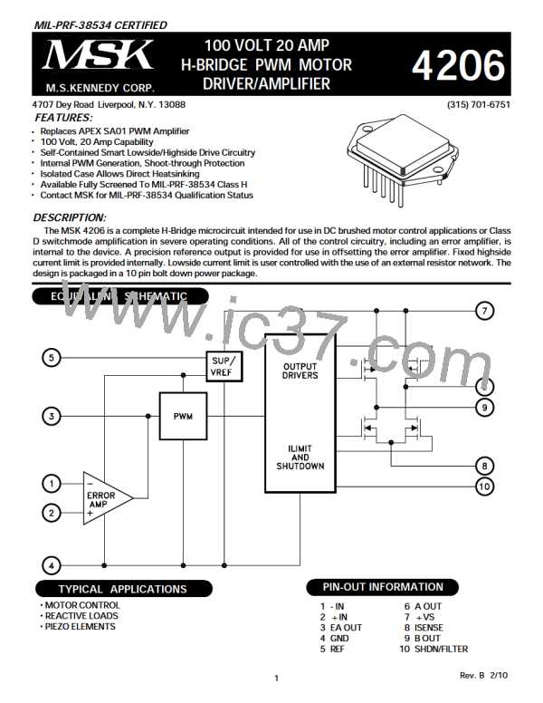
MSK 4206 PIN DESCRIPTION
+ Vs - Is the voltage supply for powering internal logic and drivers as well as H-bridge supply pin. The MOSFETS obtain the
drive current from this supply pin. The MOSFETs are rated at 100 volts. Proper bypassing to GND with sufficient capaci-
tance to suppress any voltage transients, and ensure removal of any drooping during switching, should be done as close to
the pin on the hybrid as possible.
AOUT - Is the output pin for one half of the bridge. As EA OUT goes more positive the duty cycles increases at this output.
BOUT - Is the output pin for one half of the bridge. As EA OUT goes more positive the duty cycles decreases at this output.
ISENSE - Is the connection for the bottom of the half bridge. This can have a sense resistor connection to the + Vs return
ground for current limit sensing, or can be connected directly to ground. The maximum voltage on this pin is ± 5V with
respect to GND.
GND - Is the return connection for + Vs.
+ IN - Is the non-inverting input to the internal error amplifier. This pin requires a level between 2 and 8V for proper
operation.
-IN - Is the inverting input to the internal error amplifier.
EA OUT - Is the output of the internal error amplifier. The error amplifier output is connected internally to the PWM. An
error amp output voltage higher than 5V will produce greater than 50% duty cycle pulses out of A OUT. An error amp
voltage lower than 5V will produce greater than 50% duty cycle pulses out of B OUT.
REF - Is the output of the internal precision reference. The internal reference will provide 7.5V with load current up to 5mA.
SHDN/FILTER - Is the connection for disabling all 4 output switches. SHUTDOWN high overrides all other inputs. When
taken low, everything functions normally. This pin should be grounded if not used.
Rev. B 2/10
3

 MSK [ M.S. KENNEDY CORPORATION ]