NB675 –24V, HIGH CURRENT SYNCHRONOUS BUCK CONVERTER
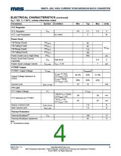
ELECTRICAL CHARACTERISTICS
VIN = 12V, TJ = 25°C, unless otherwise noted.
Parameters
Symbol Condition
Min
Typ
Max
Units
Supply Current
Supply Current (Shutdown)
IIN
IIN
VEN = 0V
EN1 = VEN1 =2V,
VFB = 0.65V, IVTT = 0A
EN1 = 0V, VEN2 = 2V,
0
1
μA
μA
V
Supply Current (In S0 Mode)
Supply Current (In S3 Mode)
300
160
400
500
V
IIN
190
220
μA
VFB = 0.65V
MOSFET
High-side Switch On Resistance
HSRDS-ON
LSRDS-ON
SWLKG
25
9
mΩ
mΩ
μA
TJ =25°C
Low-side Switch On Resistance
Switch Leakage
TJ =25°C
VEN = 0V, VSW = 0V
0
1
Current Limit
Low-side Valley Current Limit
ILIMIT
10
11
12
A
Switching frequency and minimum off time
Switching frequency
Minimum Off Time(6)
FS
400
250
500
300
600
350
kHz
ns
TOFF
Over-voltage and Under-voltage Protection
OVP Threshold
OVP Delay
VOVP
TOVPDEL
VUVP
125
55
130
2.5
60
135
65
%VREF
μs
UVP Threshold
UVP Delay
%VREF
μs
TUVPDEL
12
Reference And Soft Start
Reference Voltage
Feedback Current
Soft Start Time
VREF
IFB
598
604
10
610
50
mV
nA
VFB = 0.604V
TSS
1.6
1.95
ms
Enable And UVLO
Enable Input Low Voltage
Enable Hysteresis
VILEN
1.15
1.25
100
3
1.35
4.85
V
VEN-HYS
mV
VEN = 2V
VEN = 0V
Enable Input Current
IEN
μA
0
VCC Under Voltage Lockout
Threshold Rising
VCCVth
4.5
V
VCC Under Voltage Lockout
Threshold Hysteresis
VCCHYS
500
mV
NB675 Rev. 1.0
1/14/2013
www.MonolithicPower.com
MPS Proprietary Information. Patent Protected. Unauthorized Photocopy and Duplication Prohibited.
© 2013 MPS. All Rights Reserved.
3

 MPS [ MONOLITHIC POWER SYSTEMS ]