MP2144 – 2A, 5.5V, 1.2MHz. 40μA IQ, SYNCHRONOUS STEP-DOWN SWITCHER
APPLICATION INFORMATION
VOUT ×(V − VOUT
)
COMPONENT SELECTION
Setting the Output Voltage
IN
L1 =
V × ΔIL × fOSC
IN
The external resistor divider sets the output
voltage (see the Typical Application schematic
on page 1). The design of the feedback resistor
R1 must account for both stability and dynamic
response, and thus can not be too large or too
small. Choose an R1 value between 120kꢀ and
200kꢀ. R2 is then given by:
Where ΔIL is the inductor ripple current.
Choose an inductor current to be approximately
30% of the maximum load current. The
maximum inductor peak current is:
ΔIL
2
IL(MAX) = ILOAD
+
R1
R2 =
Vout
Selecting the Input Capacitor
−1
0.6
The input current to the step-down converter is
discontinuous, and requires a capacitor to supply
the AC current to the step-down converter while
maintaining the DC input voltage. Use low-ESR
capacitors for the best performance. Ceramic
capacitors with X5R or X7R dielectrics are
highly recommended because of their low ESR
values and small temperature coefficients. For
most applications, a 10µF capacitor is sufficient.
For higher output voltage, 47uF may be needed
to increase system stability.
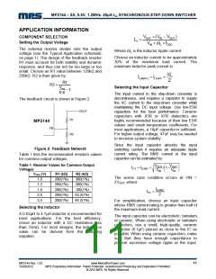
The feedback circuit is shown in Figure 2.
VOUT
R1
MP2144
FB
R2
Since the input capacitor absorbs the input
switching current it requires an adequate ripple
current rating. The RMS current in the input
capacitor can be estimated by:
Figure 2: Feedback Network
Table 1 lists the recommended resistors values
for common output voltages.
⎛
⎞
⎟
Table 1: Resistor Values for Common Output
Voltages
VOUT
VIN
VOUT
VIN
⎜
IC1 = ILOAD
×
× 1−
⎜
⎝
⎟
⎠
VOUT (V)
1.0
R1 (kΩ)
200(1%)
200(1%)
200(1%)
200(1%)
200(1%)
R2 (kΩ)
300(1%)
200(1%)
100(1%)
63.2(1%)
44.2(1%)
The worse case condition occurs at VIN =
2VOUT, where:
1.2
ILOAD
1.8
IC1
=
2
2.5
3.3
For simplification, choose an input capacitor
whose RMS current rating is greater than half of
the maximum load current.
Selecting the Inductor
A 0.82µH to 4.7µH inductor is recommended for
most applications. For the best efficiency,
chose an inductor with a DC resistance less
than 15mꢀ. For most designs, the inductance
value can be derived from the following
equation.
The input capacitor can be electrolytic, tantalum,
or ceramic. When using electrolytic or tantalum
capacitors, use a small, high-quality, ceramic
capacitor (0.1μF) placed as close to the IC as
possible. When using ceramic capacitors, make
sure that they have enough capacitance to
prevent excessive voltage ripple at the input.
MP2144 Rev. 1.03
12/20/2012
www.MonolithicPower.com
MPS Proprietary Information. Patent Protected. Unauthorized Photocopy and Duplication Prohibited.
© 2012 MPS. All Rights Reserved.
11

 MPS [ MONOLITHIC POWER SYSTEMS ]