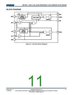
MP1907―100V, 2.5A, HIGH FREQUENCY HALF-BRIDGE GATE DRIVER
OPERATION
Under Voltage Lock Out
Switch Shoot-through Protection
When VDD or BST goes below their respective
UVLO thresholds, both DRVH and DRVL
outputs will go low to turn off both FETs. Once
VDD rises above the UVLO threshold, both
DRVH and DRVL will stay low until a rising
edge is detected on either INH or INL.
The input signals of INH and INL are controlled
independently. Input shoot-through protection
circuitry is implemented to prevent shoot-
through between the HSFET and LSFET
outputs. Only one of the FET drivers can be ON
at one time. If both INH and INL are high at the
same time, both HSFET and LSFET will be
OFF.
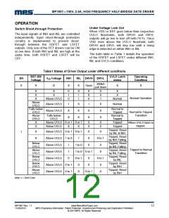
The truth table in Table 1 details the operation
of the HSFET and LSFET under different INH,
INL and UVLO conditions
Table1 States of Driver Output under different conditions
BST-SW
Voltage
UVLO Latch
status
Operating
Condition
EN
VDD Voltage
INH
INL DRVH DRVL
200kΩ
pull down
0
X
X
X
X
Open
X
X
X
X
X
X
X
0
1
0
0
1
1
0
0
0
0
0
1
X
X
Normal Operation
Above UVLO
Normal
Above
UVLO
Falls below
UVLO
Above UVLO
Above UVLO
1
X
X
0
X
X
1
0
0
0
0
0
Normal
Normal to
Tripped
Normal to
Tripped
Normal-to-Tripped
Transition
Above
UVLO
Falls below
UVLO
X
X
Above UVLO 0 or 1 0 or 1
Below UVLO
0
0
0
0
Tripped
Tripped
When UVLO latch is
tripped.
X
X
Tripped, Reset
by INL & INH
Tripped, Reset
by INH Falling
Tripped, Reset
by INL Falling
Tripped, Reset
by INL Falling
Tripped, Reset
by INL
X
X
Above UVLO 0 to 1 0 to 1
0
0
0
0
1
Above UVLO 1 to 0
1
0 to 1
Below
UVLO
Above
UVLO
Below
UVLO
Below
UVLO
Above
UVLO
Above UVLO
Above UVLO
Above UVLO
1
1
0
1 to 0
0
Tripped to Normal
Transition
1 to 0 0 to 1
0
0 to 1
0
0 to 1
0
0
Tripped, Reset
by INH
Tripped, Reset
by INH
Above UVLO 0 to 1
Above UVLO 0 to 1
0
0
0 to 1
0
Note: x = Don’t Care.
.
MP1907 Rev. 1.1
11/20/2013
www.MonolithicPower.com
MPS Proprietary Information. Patent Protected. Unauthorized Photocopy and Duplication Prohibited.
© 2013 MPS. All Rights Reserved.
12

 MPS [ MONOLITHIC POWER SYSTEMS ]