MP1498 – SYNCHRONOUS, STEP-DOWN CONVERTER WITH INTERNAL MOSFETS
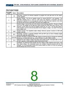
PIN FUNCTIONS
Package
Pin #
Name Description
Soft-Start. Connect an external capacitor to program the soft start time for the switch-
mode regulator.
1
SS
IN
Supply Voltage. The IN pin supplies power for internal MOSFET and regulator. The
MP1498 operates from a +4.5V to +16V input rail. Requires a low-ESR, and low-
inductance capacitor (C1) to decouple the input rail. Place the input capacitor very close
to this pin and connect it with wide PCB traces and multiple vias.
2
Switch Output. Connect this pin to the inductor and bootstrap capacitor. This pin is driven
up to the VIN voltage by the high-side switch during the PWM duty cycle ON time. The
inductor current drives the SW pin negative during the OFF time. The low-side switch’s
ON-resistance and the internal body diode fix the negative voltage. Use wide PCB traces
and multiple vias.
3
SW
System Ground. The regulated output voltage reference ground. Connect to GND with
copper and vias.
4
5
6
7
GND
BST
Bootstrap. Connect a capacitor between SW and BST pins to form a floating supply
across the high-side switch driver.
Enable. EN=high to enable the MP1498. Apply an external clock to change the switching
frequency. For automatic start-up, connect EN pin to VIN with 100Kꢀ resistor.
EN/SYNC
VCC
Internal 5V LDO Output. Powers the driver and control circuits. Decouple with a 0.1μF-
0.22μF capacitor. Avoid capacitor values that exceed 0.22μF.
Feedback. An external resistor divider from the output to GND, tapped to the FB pin, sets
the output voltage. The comparator lowers the oscillator frequency linearly with the FB
voltage. It is recommended to place the resistor divider as close to FB pin as possible.
Avoid placing vias on the FB traces.
8
FB
MP1498 Rev. 1.01
12/18/2012
www.MonolithicPower.com
MPS Proprietary Information. Patent Protected. Unauthorized Photocopy and Duplication Prohibited.
© 2012 MPS. All Rights Reserved.
8

 MPS [ MONOLITHIC POWER SYSTEMS ]