HF81 – X CAPACITOR BLEEDER
HF81 Position Selection
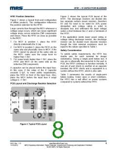
Figure 3 shows the typical PCB layout of the
HF81. The discharge resistors are divided into
two separate surface mount resistors. Resistors
R1 and R2 need to be rated for 50% power
dissipation and voltage rating in order to
dissipate loss and withstand the input voltage
under a short between the L1 and L2 terminals of
the HF81.
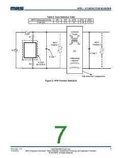
Figure 2 shows a typical front-end configuration
of offline products. The configuration influences
the position selection for the HF81.
Large currents flow through the MOV whenever a
voltage surge occurs, which can cause significant
voltage drops across inductive EMI components
and traces. Place the HF81 as close as possible
to the MOV.
If the application needs lower power rating or
voltage rating discharge resistor, the discharge
resistor can be divided more discrete resistors
though the total external resistance must be
equal to the values specified in Table 1.
1. For MOV in position 1, place the HF81
directly underneath the X cap.
2. For MOV in position 2, place the HF81 on the
same side and physically close to MOV. If the
HF81 cannot be placed at the same side as
the MOV, make sure the surge level no
higher than 1.5kV.
3. For surge levels higher than 1.5kV, place the
HF81 and MOV on the same side as the
inductive EMI components.
Safety Consideration
To satisfy safety requirements, the HF81 has
double pins for each terminal for design
redundancy. During a single point failure test, if
one pin is physically disconnected to the part or
PCB, the HF81 continues to function normally. If
one pin of part shorts to another at an opposite
terminal, the HF81 shorts and is equivalent to a
system without the HF81, which is also safe.
X capacitor can be placed before the input fuse.
In this case, if the value of the X capacitor
exceeds 0.1μF; to meet safety requirements,
place the HF81 in front of the input fuse. Also,
place the MOV before the input fuse if surge
voltage is >1.5kV.
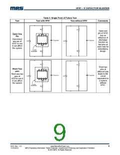
Table 3 summaries the results of single-point
failure testing. Under open or short conditions,
the HF81 has a null effect on power systems
compared to systems without the HF81.
PCB Layout and Discharge Resistor Selection
X Cap
MOV
Figure 3: Typical PCB Layout
HF81 Rev. 1.12
11/15/2012
www.MonolithicPower.com
MPS Proprietary Information. Patent Protected. Unauthorized Photocopy and Duplication Prohibited.
© 2012 MPS. All Rights Reserved.
8

 MPS [ MONOLITHIC POWER SYSTEMS ]