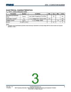
HF81 – X CAPACITOR BLEEDER
OPERATION
A smart bleeder normally works as an off device:
It consumes very little current, it always monitors
the AC line for zero crossings; whenever it
detects a zero crossing it dischargers the timer
capacitor and resets the latch circuit.
Carefully select a metal oxide varistor (MOV) and
fuse to meet safety requirements: The MOV
suppresses voltage transients. During normal
operation, a MOV with high impedance permits
only a small current. When a voltage surge
occurs, the MOV resistance reduces to a few ꢀs,
which allows the large surge current to flow
through while protecting other devices in parallel
to it.
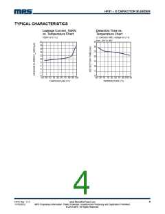
Whenever a prolonged period occurs without a
zero crossing (meaning the power supply unit
[PSU] was unplugged from the utility line), the
timer block times out and triggers the latch circuit.
The latch circuit turns on the discharging
transistors, as shown by the timing diagram in
Figure 1. The internal transistor enables the
bleed resistors, and stops when either the
voltage across the HF81 drops below 10V or the
PSU is plugged back into the utility line. This
operation allows for more X capacitor choices
and reduces the inductor cost.
There are several parameters for selecting a
MOV, including maximum-allowable voltage,
maximum clamping voltage, and the MOV max
endured energy. The maximum-allowable voltage
must exceed the maximum working voltage by
10%, 20% or the circuit needs an even higher
derating, which is determined by the power
source stability. After selecting a MOV, verify it
using V1mA, which is the voltage across the MOV
the current is 1mA. Simplified, this is:
V
1.5Vpeak 2.2VAC
(1)
1mA
Where Vpeak is the peak working voltage and VAC
is the rms working voltage.
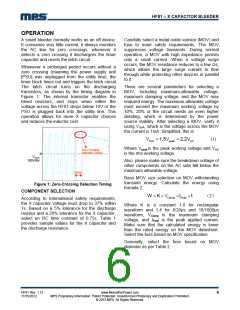
Zero Crossing
Detection Timing
VXCap
100V/div
Also, please make sure the breakdown voltage of
other components on the AC side fall below the
maximum allowable voltage.
22ms
Base MOV size selection on MOV withstanding
transient energy. Calculate the energy using
formula 2.
Figure 1: Zero-Crossing Detection Timing
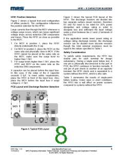
COMPONENT SELECTION
W K VClamp IPeak t
(2)
According to international safety requirements,
the X capacitor voltage must drop to 37% within
1s. Based on a 5% tolerance for the discharge
resistor and a 20% tolerance for the X capacitor,
select an RC time constant of 0.75s. Table 1
provides sample values for the X capacitor and
the discharge resistance.
Where K is a constant 1.0 for rectangular
waveform and 1.4 for 8/20µs and 10/1000µs
waveform, VClamp is the maximum clamping
voltage, and IPeak is the peak applied current.
Make sure that the calculated energy is lower
than the rated energy on the MOV datasheet.
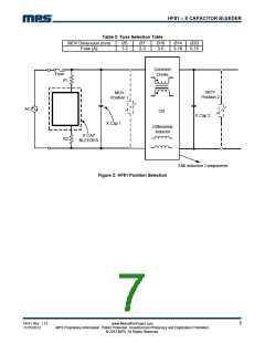
Select the fuse based on MOV specification.
Generally, select the fuse based on MOV
diameter as per Table 2.
HF81 Rev. 1.12
11/15/2012
www.MonolithicPower.com
MPS Proprietary Information. Patent Protected. Unauthorized Photocopy and Duplication Prohibited.
© 2012 MPS. All Rights Reserved.
6

 MPS [ MONOLITHIC POWER SYSTEMS ]