C6
Z5
L3
+
B
B
+
V
C7
C8
CC
L1
L2
–
C4
Z6
Z1
Z2
Z3
Z4
DUT
C5
C2
C3
C1
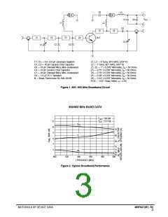
C1, C5 — 0.8–8.0 pF Johanson Gigatrim
C2, C3 — 10 pF Ceramic Chip Capacitor
C6 — 91 pF Clamped Mica, Mini–Underwood
C4 — 47 pF Ceramic Chip Capacitor
C7 — 91 pF Clamped Mica, Mini–Underwood
C8 — 1.0 µF 25 V Tantalum
L1, L2 — 4 Turns, #21 AWG, 5/32″ ID
L3 — 7 Turns, #21 AWG, 5/32″ ID
Z1, Z2 — 1″ x 0.078″ Microstrip, Z = 50 Ohms
o
Z3 — 0.25″ x 0.078″ Microstrip, Z = 50 Ohms
o
Z4 — 0.15″ x 0.078″ Microstrip, Z = 50 Ohms
o
Z5 — 0.30″ x 0.078″ Microstrip, Z = 50 Ohms
o
B — Bead, Ferroxcube 56–590–65/3B
Z6 — 1.63″ x 0.078″ Microstrip, Z = 50 Ohms
o
PCB — 1/32″ Glass Teflon, ε = 2.56
r
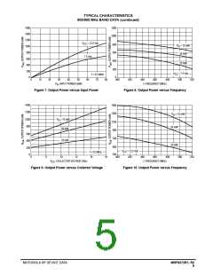
Figure 1. 800–900 MHz Broadband Circuit
800/900 MHz BAND DATA
P
V
= 750 mW
= 12.5 Vdc
out
CC
12
10
8
G
PE
70
60
50
η
c
6
4
10
15
2
IRL
840
20
25
800
820
860
880
900
f, FREQUENCY (MHz)
Figure 2. Typical Broadband Performance
MOTOROLA RF DEVICE DATA
MRF8372R1, R2
3

 MOTOROLA [ MOTOROLA ]