Freescale Semiconductor, Inc.
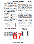
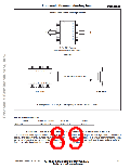
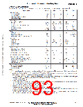
Positive Acceleration Sensing Direction
1
2
3
4
5
6
7
8
16
15
14
13
12
11
10
9
–X
+X
16–Pin SOIC Package
N/C pins are recommended to be left FLOATING
Top View
8
7 6 5 4 3 2 1
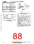
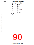
Direction of Earth’s gravity field.*
9 10 11 12 13 14 15 16
Front View
Side View
* When positioned as shown, the Earth’s gravity will result in a positive 1g output
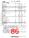
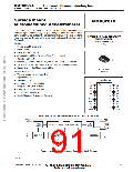
ORDERING INFORMATION
Device
MMA2202D
Temperature Range
Case No.
Package
40 to +85°C
Case 475–01
SOIC–16
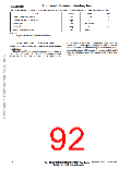
MINIMUM RECOMMENDED FOOTPRINT FOR SURFACE MOUNTED APPLICATIONS
Surface mount board layout is a critical portion of the total
design. The footprint for the surface mount packages must
be the correct size to ensure proper solder connection inter-
face between the board and the package. With the correct
footprint, the packages will self–align when subjected to a
solder reflow process. It is always recommended to design
boards with a solder mask layer to avoid bridging and short-
ing between solder pads.
Motorola Sensor Device Data
www.motorola.com/semiconductors
2–53
For More Information On This Product,
Go to: www.freescale.com

 MOTOROLA [ MOTOROLA ]