MAXIMUM RATINGS* (Voltages Referenced to V
)
SS
Symbol
Parameter
DC Supply Voltage
Value
Unit
V
This device contains protection circuitry to
guard against damage due to high static
voltages or electric fields. However, pre-
cautions must be taken to avoid applications of
any voltage higher than maximum rated volt-
ages to this high–impedance circuit. For proper
V
DD
– 0.5 to + 18.0
V , V
Input or Output Voltage (DC or Transient)
– 0.5 to V
DD
+ 0.5
V
in out
I , I
Input or Output Current (DC or Transient),
per Pin
± 10
mA
in out
operation, V and V
should be constrained
in out
P
D
Power Dissipation, per Package†
Storage Temperature
500
mW
C
to the range V
(V or V
)
V
DD
.
SS in out
Unused inputs must always be tied to an
appropriate logic voltage level (e.g., either V
T
stg
– 65 to + 150
260
SS
or V ). Unused outputs must be left open.
T
L
Lead Temperature (8–Second Soldering)
C
DD
* Maximum Ratings are those values beyond which damage to the device may occur.
†Temperature Derating:
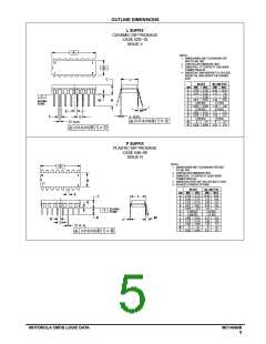
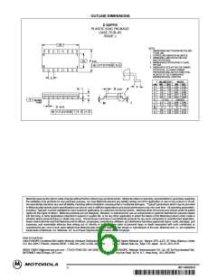
Plastic “P and D/DW” Packages: – 7.0 mW/ C From 65 C To 125 C
Ceramic “L” Packages – 12 mW/ C From 100 C To 125 C
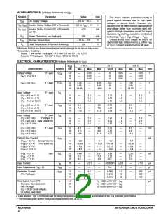
ELECTRICAL CHARACTERISTICS (Voltages Referenced to V
)
SS
– 55 C
25 C
Typ #
125 C
V
Vdc
DD
Characteristic
Output Voltage
Symbol
Unit
Min
Max
Min
Max
Min
Max
“0” Level
“1” Level
“0” Level
V
OL
5.0
10
15
—
—
—
0.05
0.05
0.05
—
—
—
0
0
0
0.05
0.05
0.05
—
—
—
0.05
0.05
0.05
V
V
in
= V
DD
or 0
V
in
= 0 or V
V
OH
5.0
10
15
4.95
9.95
14.95
—
—
—
4.95
9.95
14.95
5.0
10
15
—
—
—
4.95
9.95
14.95
—
—
—
V
V
DD
Input Voltage
(V = 4.5 or 0.5 V)
V
IL
5.0
10
15
—
—
—
1.5
3.0
4.0
—
—
—
2.25
4.50
6.75
1.5
3.0
4.0
—
—
—
1.5
3.0
4.0
O
(V = 9.0 or 1.0 V)
O
(V = 13.5 or 1.5 V)
O
(V = 0.5 or 4.5 V)
O
“1” Level
V
IH
5.0
10
15
3.5
7.0
11.0
—
—
—
3.5
7.0
11.0
2.75
5.50
8.25
—
—
—
3.5
7.0
11.0
—
—
—
V
(V = 1.0 or 9.0 V)
O
(V = 1.5 or 13.5 V)
O
Input Voltage
(V = 4.5 Vdc)
“0” Level
(For Input 11
V
IL
Vdc
5.0
10
15
—
—
—
1.0
2.0
2.5
—
—
—
2.25
4.50
6.75
1.0
2.0
2.5
—
—
—
1.0
2.0
2.5
O
(V = 9.0 Vdc) and Output 10)
O
(V = 13.5 Vdc)
O
(V = 0.5 Vdc)
O
“1” Level
V
5.0
10
15
4.0
8.0
12.5
—
—
—
4.0
8.0
12.5
2.75
5.50
8.25
—
—
—
4.0
8.0
12.5
—
—
—
Vdc
mA
IH
(V = 1.0 Vdc)
O
(V = 1.5 Vdc)
O
Output Drive Current
I
OH
(V
OH
(V
OH
(V
OH
(V
OH
= 2.5 V)
= 4.6 V)
= 9.5 V)
= 13.5 V)
(Except Source
Pins 9 and 10)
5.0
5.0
10
– 3.0
– 0.64
– 1.6
– 4.2
—
—
—
—
– 2.4
– 0.51
– 1.3
– 3.4
– 4.2
– 0.88
– 2.25
– 8.8
—
—
—
—
– 1.7
– 0.36
– 0.9
– 2.4
—
—
—
—
15
(V
OL
(V
OL
(V
OL
= 0.4 V)
= 0.5 V)
= 1.5 V)
Sink
I
5.0
10
15
0.64
1.6
4.2
—
—
—
0.51
1.3
3.4
0.88
2.25
8.8
—
—
—
0.36
0.9
2.4
—
—
—
mA
OL
Input Current
I
15
—
—
—
± 0.1
—
—
±0.00001
± 0.1
—
—
± 1.0
µA
pF
µA
in
Input Capacitance (V = 0)
in
C
—
5.0
7.5
—
in
Quiescent Current
(Per Package)
I
5.0
10
15
—
—
—
5.0
10
20
—
—
—
0.005
0.010
0.015
5.0
10
20
—
—
—
150
300
600
DD
Total Supply Current**†
(Dynamic plus Quiescent,
Per Package)
I
T
5.0
10
15
I
T
I
T
I
T
= (0.25 µA/kHz) f + I
= (0.54 µA/kHz) f + I
= (0.85 µA/kHz) f + I
µA
DD
DD
DD
(C = 50 pF on all outputs,
L
all buffers switching)
# Data labelled “Typ” is not to be used for design purposes but is intended as an indication of the IC’s potential performance.
**The formulas given are for the typical characteristics only at 25 C.
MC14060B
2
MOTOROLA CMOS LOGIC DATA

 MOTOROLA [ MOTOROLA ]