MC1391
MAXIMUM RATINGS (T = +25°C, unless otherwise noted.)
A
Rating
Supply Current
Value
40
Unit
mAdc
Vdc
Output Voltage
40
Output Current
30
mAdc
Sync Input Voltage (Pin 3)
Flyback Input Voltage (Pin 4)
5.0
5.0
V
V
pp
pp
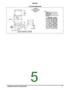
Power Dissipation (Package Limitation)
Plastic Package
625
5.0
mW
mW/°C
Derate above T = +25°C
A
Operating Temperature Range (Ambient)
Storage Temperature Range
0 to +70
°C
°C
–65 to +150
ELECTRICAL CHARACTERISTICS (T = +25°C, unless otherwise noted. See Test Circuit of Figure 2, all switches in position 1.)
A
Characteristics
Min
8.0
–
Typ
8.6
20
Max
9.4
–
Unit
Vdc
Regulated Voltage (Pin 6)
Supply Current (Pin 6)
mAdc
Vdc
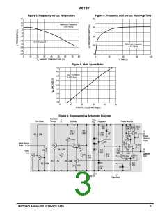
Collector–Emitter Saturation Voltage (Output Transistor Q1 in Figure 6)
(I = 20 mA, Pin 1 ) Vdc
–
–
–
–
0.15
2.0
0.25
C
Voltage (Pin 4)
–
–
–
Vdc
Hz
Hz
µs
Oscillator Pull–in Range (Adjust R in Figure 2)
±300
±900
H
Oscillator Hold–in Range (Adjust R in Figure 2)
H
Static Phase Error
(∆f = 300 Hz)
–
–
0.5
–
–
Free–running Frequency Supply Dependance
(S1 in position 2)
Hz/Vdc
±3.0
Phase Detector Leakage (Pin 5)
(All switches in position 2)
µA
–
–
–
–
±1.0
5.0
Sync Input Voltage (Pin 3)
2.0
1.0
V
V
pp
Sawtooth Input Voltage (Pin 4)
3.0
pp
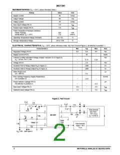
Figure 2. Test Circuit
0.1
µ
F
3.3k
–
2
+
0.1
µ
F
3.3k
5
6
7
S2
S3
4
2
+
1
2
S1
µA
0.1
µ
F
1
Pulse Generator
Sync Pulse =
+4.0V
3
2
–20 V, 5.0
µs,
1
39k
0.003
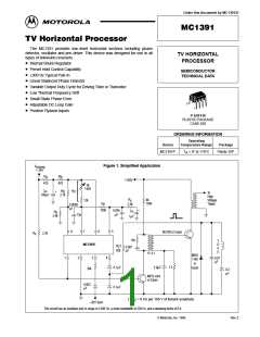
MC1391P
f
= 15.750 Hz
150k
O
R
H
µF
12k
Output
Pulse
+30V
3.0k
6800pF
1.0k
1.0k
Pulse Generator
Output = +50 V
8
1
12 µs
V
2.0k
M
V
+30V (See Figure 5)
CC
2
MOTOROLA ANALOG IC DEVICE DATA

 MOTOROLA [ MOTOROLA ]