PDF
最近搜索
热门搜索
发布采购

| 型号: | KM241 |
| PDF下载: | 下载PDF文件 查看货源 |
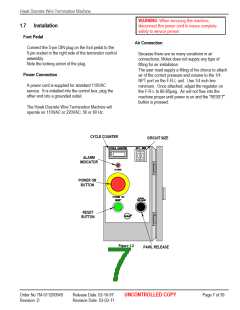
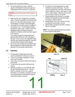
| 内容描述: | 鹰导线端子机操作手册 [Hawk Discrete Wire Termination Machine Operation Manual] |
| 分类和应用: | |
| 文件页数/大小: | 39 页 / 2732 K |
| 品牌: |  MOLEX [ Molex ] MOLEX [ Molex ] |
专业IC领域供求交易平台:提供全面的IC Datasheet资料和资讯,Datasheet 1000万数据,IC品牌1000多家。