MITSUBISHI MICROCOMPUTERS
3827 Group
SINGLE-CHIP 8-BIT CMOS MICROCOMPUTER
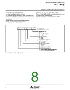
[CPU Mode Register (CPUM)] 003B16
The CPU mode register contains the stack page selection bit and
the internal system clock selection bit.
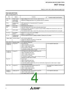
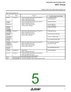
FUNCTIONAL DESCRIPTION
Central Processing Unit (CPU)
The 3827 group uses the standard 740 family instruction set. Re-
fer to the table of 740 family addressing modes and machine
instructions or the 740 Family Software Manual for details on the
instruction set.
The CPU mode register is allocated at address 003B16.
Machine-resident 740 family instructions are as follows:
The FST and SLW instruction cannot be used.
The STP, WIT, MUL, and DIV instruction can be used.
b7
b0
CPU mode register
(CPUM (CM) : address 003B16
)
Processor mode bits
b1 b0
0
0
1
1
0 : Single-chip mode
1 :
0 :
1 :
Not available
Stack page selection bit
0 : 0 page
1 : 1 page
Not used (returns “1” when read)
(Do not write “0” to this bit.)
Port XC switch bit
0 : Stop oscillating
1 : XCIN, XCOUT
Main clock ( XIN-XOUT) stop bit
0 : Oscillating
1 : Stopped
Main clock division ratio selection bit
0 : XIN/2 (high-speed mode)
1 : XIN/8 (middle-speed mode)
Internal system clock selection bit
0 : XIN-XOUT selected (middle-/high-speed mode)
1 : XCIN-XCOUT selected (low-speed mode)
Fig. 6 Structure of CPU mode register
8

 MITSUBISHI [ Mitsubishi Group ]