MITSUBISHI MICROCOMPUTERS
3822 Group
SINGLE-CHIP 8-BIT CMOS MICROCOMPUTER
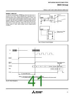
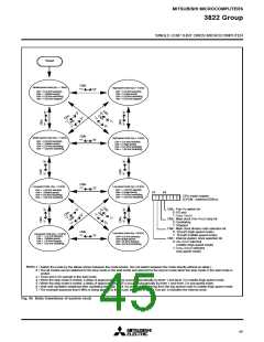
Reset
CM6
Middle-speed mode (f(φ) = 1 MHz)
High-speed mode (f(φ) = 4 MHz)
“1”
“0”
CM7 = 0 (8 MHz selected)
CM6 = 1 (Middle-speed)
CM5 = 0 (8 MHz oscillating)
CM4 = 0 (32 kHz stopped)
CM7 = 0 (8 MHz selected)
CM6 = 0 (High-speed)
CM5 = 0 (8 MHz oscillating)
CM4 = 0 (32 kHz stopped)
CM6
Middle-speed mode (f(φ) = 1 MHz)
High-speed mode (f(φ) = 4 MHz)
“1”
“0”
CM7 = 0 (8 MHz selected)
CM6 = 1 (Middle-speed)
CM5 = 0 (8 MHz oscillating)
CM4 = 1 (32 kHz oscillating)
CM7 = 0 (8 MHz selected)
CM6 = 0 (High-speed)
CM5 = 0 (8 MHz oscillating)
CM4 = 1 (32 kHz oscillating)
CM6
Low-speed mode (f(φ) =16 kHz)
Low-speed mode (f(φ) = 16 kHz)
“1”
“0”
CM7 = 1 (32 kHz selected)
CM6 = 0 (High-speed)
CM5 = 0 (8 MHz oscillating)
CM4 = 1 (32 kHz oscillating)
CM7 = 1 (32 kHz selected)
CM6 = 1 (Middle-speed)
CM5 = 0 (8 MHz oscillating)
CM4 = 1 (32 kHz oscillating)
b7
b4
CPU mode register
(CPUM : address 003B16)
CM4 : Port Xc switch bit
0: I/O port
1: XCIN, XCOUT
CM5 : Main clock (XIN–XOUT) stop bit
0: Oscillating
1: Stopped
CM6 : Main clock division ratio selection bit
0: f(XIN)/2 (high-speed mode)
1: f(XIN)/8 (middle-speed mode)
CM7 : Internal system clock selection bit
0: XIN–XOUT selected
CM6
Low-speed mode (f(φ) =16 kHz)
Low-speed mode (f(φ) = 16 kHz)
CM7 = 1 (32 kHz selected)
CM6 = 1 (Middle-speed)
CM5 = 1 (8 MHz stopped)
CM4 = 1 (32 kHz oscillating)
“1”
“0”
CM7=1(32 kHz selected)
CM6=0(High-speed)
CM5=1(8 MHz stopped)
CM4=1(32 kHz oscillating)
(middle-/high-speed mode)
1: XCIN–XCOUT selected
(low-speed mode)
Notes
1 : Switch the mode by the allows shown between the mode blocks. (Do not switch between the mode directly without an allow.)
2 : The all modes can be switched to the stop mode or the wait mode and returned to the source mode when the stop mode or the wait mode is
ended.
3 : Timer and LCD operate in the wait mode.
4 : When the stop mode is ended, a delay of approximately 1 ms occurs automatically by timer 1 and timer 2 in middle-/high-speed mode.
5 : When the stop mode is ended, a delay of approximately 0.25 s occurs automatically by timer 1 and timer 2 in low-speed mode.
6 : Wait until oscillation stabilizes after oscillating the main clock XIN before the switching from the low-speed mode to middle-/high-speed mode.
7 : The example assumes that 8 MHz is being applied to the XIN pin and 32 kHz to the XCIN pin. φ indicates the internal clock.
Fig. 45 State transitions of system clock
45

 MITSUBISHI [ Mitsubishi Group ]