MITSUBISHI MICROCOMPUTERS
7477/7478 GROUP
SINGLE-CHIP 8-BIT CMOS MICROCOMPUTER
Table 2. Pin function in EPROM mode
M37477E8, M37478E8
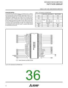
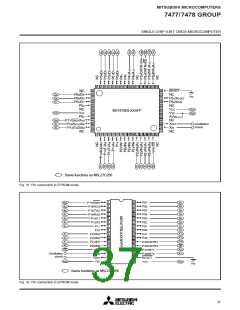
EPROM MODE
The M37477E8, M37478E8 feature an EPROM mode in addition
to its normal modes. When the RESET signal level is low (“L”), the
chip automatically enters the EPROM mode. Table 2 lists the cor-
respondence between pins and Figure 30 to 32 give the pin
connection in the EPROM mode. When in the EPROM mode,
ports P0, P11 to P17, P20 to P23, P3, P40, P41 and VREF are used
for the PROM (equivalent to the M5L27C256). When in this mode,
the built-in PROM can be written to or read from using these pins
in the same way as with the M5L27C256K. The oscillator should
be connected to the XIN and XOUT pins, or external clock should
be connected to the XIN pin.
M5L27C256K
VCC
VPP
VSS
VCC
VCC
VPP
VSS
P33
VSS
Ports P11 – P17,
Address input
P20 – P23, P30,
A0 – A14
P31, P40, P41
Port P0
VREF
Data I/O
CE
D0 – D7
CE
OE
P32
OE
1
42
P52
P53
2
3
4
5
6
7
8
9
41
40
A10
A9
D7
D6
P07
P17/SRDY
P16/SCLK
P15/TXD
P14/RXD
P13/T1
P12/T0
P11
P06
39
38
37
36
35
34
33
32
31
30
29
28
27
26
25
24
23
22
A8
P05
D5
D4
A7
A6
A5
A4
P04
D3
D2
D1
D0
P03
P02
P01
P10
P00
10
11
12
13
14
15
16
17
18
19
20
21
P27/IN7
P26/IN6
P25/IN5
P24/IN4
P23/IN3
P22/IN2
P21/IN1
P20/IN0
VREF
P43
P42
A14
A13
VPP
OE
P41
P40
A3
A2
A1
P33/CNTR1
P32/CNTR0
P31/INT1
P30/INT0
RESET
P51/XCOUT
P50/XCIN
VCC
A12
A11
A0
CE
Oscillation
circuit
XIN
VSS
XOUT
VSS
VCC
VSS
: Same functions as M5L27C256
Fig. 30 Pin connection in EPROM mode
36

 MITSUBISHI [ Mitsubishi Group ]