MITSUBISHI MICROCOMPUTERS
M37270MF-XXXSP
M37270EF-XXXSP, M37270EFSP
SINGLE-CHIP 8-BIT CMOS MICROCOMPUTER with CLOSED CAPTION DECODER
and ON-SCREEN DISPLAY CONTROLLER
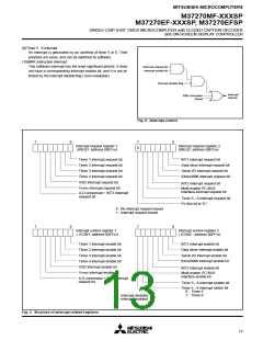
MEMORY
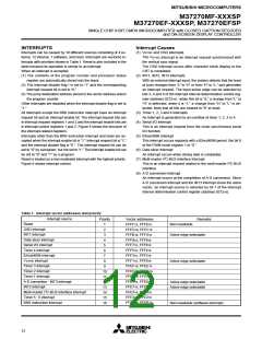
Interrupt Vector Area
The interrupt vector area contains reset and interrupt vectors.
Special Function Register (SFR) Area
The special function register (SFR) area in the zero page contains
control registers such as I/O ports and timers.
Zero Page
The 256 bytes from addresses 000016 to 00FF16 are called the zero
page area. The internal RAM and the special function registers (SFR)
are allocated to this area.
RAM
RAM is used for data storage and for stack area of subroutine calls
and interrupts.
The zero page addressing mode can be used to specify memory and
register addresses in the zero page area. Access to this area with
only 2 bytes is possible in the zero page addressing mode.
ROM
ROM is used for storing user programs as well as the interrupt vector
area.
Special Page
The 256 bytes from addresses FF0016 to FFFF16 are called the spe-
cial page area. The special page addressing mode can be used to
specify memory addresses in the special page area. Access to this
area with only 2 bytes is possible in the special page addressing
mode.
RAM for OSD
RAM for display is used for specifying the character codes and col-
ors to display.
ROM for OSD
ROM for display is used for storing character data.
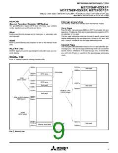
000016
1000016
Not used
1080016
Zero page
00C016
00FF16
SFR1 area
RAM
(1024 bytes)
020016
023F16
SFR2 area
Not used
1567F16
Not used
030016
053F16
1800016
ROM for OSD
(14464 bytes)
Not used
080016
0FFF16
100016
RAM for OSD (Note)
(1920 bytes)
ROM
(60 K bytes)
FF0016
FFDE16
1E43F16
Not used
Special page
Interrupt vector area
1FFFF16
FFFF16
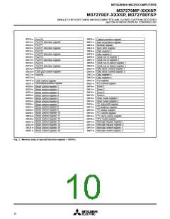
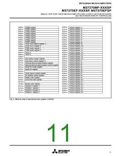
Fig. 2. Memory map
9

 MITSUBISHI [ Mitsubishi Group ]