Mitsubishi microcomputers
M16C / 62 Group
SINGLE-CHIP 16-BIT CMOS MICROCOMPUTER
Appendix Standard Serial I/O Mode (Flash Memory Version)
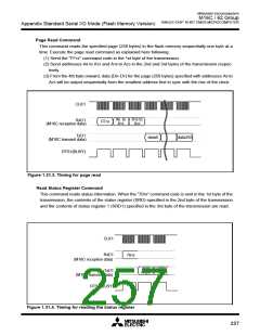
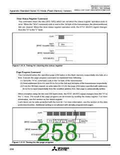
Clear Status Register Command
This command clears the bits (SR3–SR5) which are set when the status register operation ends in
error. When the “5016” command code is sent in the 1st byte of the transmission, the aforementioned
bits are cleared. When the clear status register operation ends, the RTS1 (BUSY) signal changes
from the “H” to the “L” level.
CLK1
RxD1
5016
(M16C reception data)
TxD1
(M16C transmit data)
RTS1(BUSY)
Figure 1.31.5. Timing for clearing the status register
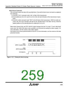
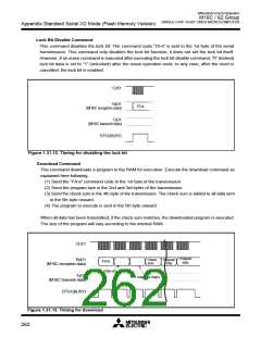
Page Program Command
This command writes the specified page (256 bytes) in the flash memory sequentially one byte at a
time. Execute the page program command as explained here following.
(1) Send the “4116” command code in the 1st byte of the transmission.
(2) Send addresses A
(3) From the 4th byte onward, as write data (D
to A23 is input sequentially from the smallest address first, that page is automatically written.
8
to A15 and A16 to A23 in the 2nd and 3rd bytes of the transmission respectively.
0
–D ) for the page (256 bytes) specified with addresses
7
A
8
When reception setup for the next 256 bytes ends, the RTS1 (BUSY) signal changes from the “H” to
the “L” level. The result of the page program can be known by reading the status register. For more
information, see the section on the status register.
Each block can be write-protected with the lock bit. For more information, see the section on the data
protection function. Additional writing is not allowed with already programmed pages.
CLK1
RxD1
(M16C reception data)
A
8
to
A
16 to
4116
data0
data255
A
15
A23
TxD1
(M16C transmit data)
RTS1(BUSY)
Figure 1.31.6. Timing for the page program
258

 MITSUBISHI [ Mitsubishi Group ]