SL2015
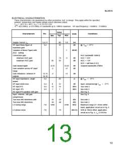
ELECTRICAL CHARACTERISTICS
These characteristics are guaranteed by either production test or design. They apply within the specified
ambient temperature and supply voltage unless otherwise stated.
TAMB = -20°C to + 80°C, VCC= + 4.75V to 5·25V.
IF = 403.25MHz or 479.5MHz; IF bandwidth up to 54MHz maximum. RF input frequency = 950MHz -2150MHz.
Value
Characteristic
Pin
Conditions
Units
Typ
Max
Min
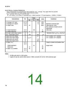
LO leakage to RF input
3,4,7,8
7,8,12
15,16
-30
-10
dBm
dBm
LO leakage to IF outputs
LO output drive
Maximum conversion gain
Differential into 100Ω,
NB, synthesiser should be driven
differentially
92
dBµV
LO output impedance
15,16
15,16
20
100
Ω
Differential
LO output return loss
8
dB
AGC gain control slope variation
AGC control input current
Output select low voltage
Output select high voltage
Output select low current
Output select high current
IF output 1 & 2
Monotonic from VEE to VCC. See Fig. 9
20
-250
250
0.7
µA
V
10
O/P 2 enabled, O/P 1 disabled
O/P 1 enabled, O/P 2 disabled
10
VCC-0.7
V
10
-50
µA
µA
10
200
12,13,
18,19
Output in enabled and disabled state
Single ended
Output impedance
Return loss
50
Ω
12
30
dB
dB
IF output 1 to 2 isolation
12,13
18,19
Notes:
1. All dBm units refer to a 50Ω system
2. Applies for any two carriers within band at -19dBm, and with AGC set for +5dB conversion gain.
14

 MITEL [ MITEL NETWORKS CORPORATION ]