MT9076
Preliminary Information
3.3.1
Basic Frame Alignment
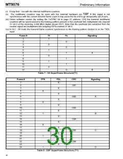
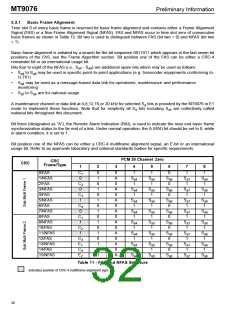
Time slot 0 of every basic frame is reserved for basic frame alignment and contains either a Frame Alignment
Signal (FAS) or a Non-Frame Alignment Signal (NFAS). FAS and NFAS occur in time slot zero of consecutive
basic frames as shown in Table 12. Bit two is used to distinguish between FAS (bit two = 0) and NFAS (bit two
= 1).
Basic frame alignment is initiated by a search for the bit sequence 0011011 which appears in the last seven bit
positions of the FAS, see the Frame Algorithm section. Bit position one of the FAS can be either a CRC-4
remainder bit or an international usage bit.
Bits four to eight of the NFAS (i.e., S - S ) are additional spare bits which may be used as follows:
a4
a8
•
•
•
S
to S may be used in specific point-to-point applications (e.g. transcoder equipments conforming to
a4 a8
G.761)
S
may be used as a message-based data link for operations, maintenance and performance
a4
monitoring
S
to S are for national usage
a5
a8
A maintenance channel or data link at 4,8,12,16,or 20 kHz for selected S bits is provided by the MT9076 in E1
a
mode to implement these functions. Note that for simplicity all S bits including Sa4 are collectively called
a
national bits throughout this document.
Bit three (designated as “A”), the Remote Alarm Indication (RAI), is used to indicate the near end basic frame
synchronization status to the far end of a link. Under normal operation, the A (RAI) bit should be set to 0, while
in alarm condition, it is set to 1.
Bit position one of the NFAS can be either a CRC-4 multiframe alignment signal, an E-bit or an international
usage bit. Refer to an approvals laboratory and national standards bodies for specific requirements.
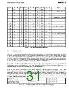
PCM 30 Channel Zero
CRC
CRC
Frame/Type
1
2
3
4
5
6
7
8
0/FAS
C
0
1
0
1
0
1
0
1
0
1
0
1
0
1
0
1
0
A
0
1
1
0
1
1
1
1/NFAS
2/FAS
0
S
S
S
S
S
a8
a4
a5
a6
a7
C
1
1
0
1
1
2
3/NFAS
4/FAS
0
A
0
S
S
S
S
S
a8
a4
a5
a6
a7
C
1
1
0
1
1
3
5/NFAS
6/FAS
1
A
0
S
S
S
S
S
a8
a4
a5
a6
a7
C
1
1
0
1
1
4
7/NFAS
8/FAS
0
A
0
S
S
S
S
S
a8
a4
a5
a6
a7
C
1
1
0
1
1
1
9/NFAS
10/FAS
11/NFAS
12/FAS
13/NFAS
14/FAS
15/NFAS
1
A
0
S
S
S
S
S
a8
a4
a5
a6
a7
C
1
1
0
1
1
2
1
A
0
S
S
S
S
S
a8
a4
a5
a6
a7
C
1
1
0
1
1
3
E
A
0
S
S
S
S
S
a8
1
a4
a5
a6
a7
C
1
1
0
1
1
4
E
A
S
S
S
S
S
a8
2
a4
a5
a6
a7
Table 11 - FAS and NFAS Structure
indicates position of CRC-4 multiframe alignment signa
28

 MITEL [ MITEL NETWORKS CORPORATION ]