Preliminary Information
MT9076
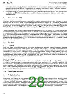
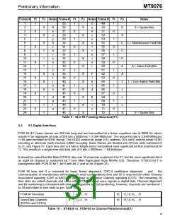
It should be noted that the Mitel ST-BUS has 32 channels numbered 0 to 31. When mapping to the DS1
payload only the first 24 time slots and the last (time slot 31, for the overhead bit) of an ST-BUS are used (see
Table 6). All unused channels are tristate.
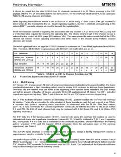
When signaling information is written to the MT9076 in T1 mode using ST-BUS control links (as opposed to
direct writes by the microport to the on - board signaling registers), the CSTi channels corresponding to the
selected DSTi channels streams are used to transmit the signaling bits.
Since the maximum number of signaling bits associated with any channel is 4 (in the case of ABCD), only half
a CSTi channel is required for sourcing the signaling bits. The choice of which half of the channel to use is
selected by the control bit MSN (page 01H address 14H). The same control bit selects which half of the CSTo
channel will contain receive signaling information (the other nibble in the channel being tristate). Unused
channels are tristate.
The most significant bit of an eight bit ST-BUS channel is numbered bit 7 (see Mitel Application Note MSAN-
126). Therefore, ST-BUS bit 7 is synonymous with DS1 bit 1; bit 6 with bit 2: and so on.
DS1 Timeslots
1
0
2
1
3
2
4
3
5
4
6
5
7
6
8
7
9
7
10 11 12 13 14 15
16
15
Voice/Data Channels
(DSTi/o and CSTi/o)
9
10 11 12 13 14
Ds1 Timeslots
17 18 19 20 21 22 23 24
-
-
-
-
-
-
-
-
Voice/Data Channels
(DSTi/o and CSTi/o)
16 17 18 19 20 21 22 23 24 25 26 27 28 29 30
31
Sbit
x
x
x
x
x
x
x
Table 6 - ST-BUS vs. DS1 to Channel Relationship(T1)
Frame and Superframe Structure in T1 mode
3.2
3.2.1
Multiframing
In T1 mode, DS1 trunks contain 24 bytes of serial voice/data channels bundled with an overhead bit. The frame
overhead bit contains a fixed repeating pattern used to enable DS1 receivers to deliniate frame boundaries.
Overhead bits are inserted once per frame at the beginning of the transmit frame boundary. The DS1 frames
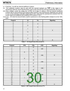
are further grouped in bundles of frames, generally 12 (for D4 applications) or 24 frames (for ESF - extended
superframe applications) deep. Table 7 and 8 illustrate the D4 and ESF frame structures respectively.
For D4 links the frame structure contains an alternating 101010... pattern inserted into every second overhead
bit position. These bits are intended for determination of frame boundaries, and they are referred to as Ft bits.
A separate fixed pattern, repeating every superframe, is interleaved with the Ft bits. This fixed pattern
(001110), is used to deliniate the 12 frame superframe. These bits are referred to as the Fs bits. In D4 frames
# 6 and #12, the LSB of each channel byte may be replaced with A bit (frame #6) and B bit (frame #12)
signaling information.
For ESF links the 6 bit framing pattern 001011, inserted into every 4th overhead bit position, is used to
deliniate both frame and superframe boundaries. Frames #6, 12, 18 and 24 contain the A, B, C and D signaling
bits, respectively. A 4 kHz data link is embedded in the overhead bit position, interleaved between the framing
pattern sequence (FPS) and the transmit CRC-6 remainder (from the calculation done on the previous
superframe), see Table 8.
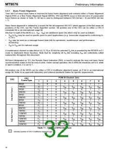
The SLC-96 frame structure is similar to the D4 frame structure, except a facility management overlay is
superimposed over the erstwhile Fs bits, see Table 9.
The protocol appropriate for the application is selected via the Framing Mode Selection Word, address 10H of
Master Control page 1. In T1 mode, MT9076 is capable of generating the overhead bit framing pattern and (for
ESF links) the CRC remainder for transmission onto the DS1 trunk. The beginning of the transmit multiframe
may be determined by any of the following criteria:
25

 MITEL [ MITEL NETWORKS CORPORATION ]