Preliminary Information
MT9075A
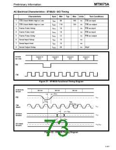
AC Electrical Characteristics - ST-BUS / GCI Timing
Characteristic
Sym
Min
Typ
Max Units
Test Conditions
1
2
3
4
5
6
7
8
C4b Clock Width High or Low
C4b Clock Width High or Low
Frame Pulse Setup
t4WI
t4WO
tFPS
tFPH
tFPD
tSIS
80
110
10
10
12
15
15
50
164
135
ns C4b as input
ns C4b as output
ns F0b as input
ns F0b as input
ns F0b as output
ns
Frame Pulse Hold
Frame Pulse Delay
Serial Input Setup
Serial Input Hold
tSIH
ns
Serial Output Delay
tSOD
ns 50pF
ST-BUS
Bit Cells
Channel 31
Bit 0
Channel 0
Bit 7
Channel 0
Bit 6
Channel 0
Bit 5
F0b
C4b
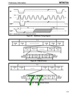
Figure 21 - ST-BUS Functional Timing Diagram
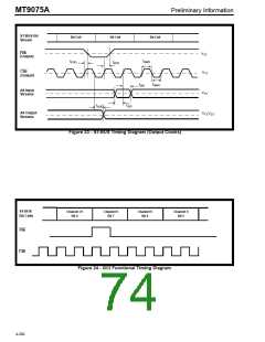
ST-BUS Bit
Stream
Bit Cell
Bit Cell
Bit Cell
t
FPH
F0b
V
V
TT
t
FPS
t
4WI
t
4WI
C4b
(Input)
TT
t
SIH
All Input
Streams
V
TT
t
SIS
t
SOD
All Output
Streams
V
V
TT, CT
Figure 22 - ST-BUS Timing Diagram
4-201

 MITEL [ MITEL NETWORKS CORPORATION ]