MT8986
Pin Description (continued)
Pin #
Name
Description
40
44
44
DIP PLCC QFP
31 35
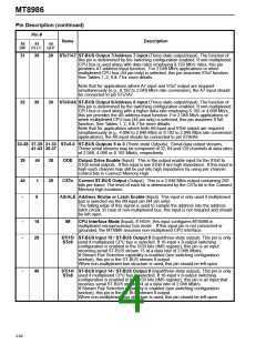
29 STo7/A7 ST-BUS Output 7/Address 7 input (Three-state output/input). The function of
this pin is determined by the switching configuration enabled. If non-multiplexed
CPU bus is used along with data rates employing 8.192 Mb/s rates, this pin
provides A7 address input function. For 2.048 Mb/s applications or when
multiplexed CPU bus (44 pin only) is selected, this pin assumes STo7 function.
See Tables 1, 2, 6 & 7 for more details.
Note that for applications where A7 input and STo7 output are required
simultaneously (e.g., 8.192 to 2.048 Mb/s rate conversion), the A7 input should
be connected to pin STi7/A7.
32
36
30 STo6/A6 ST-BUS Output 6/Address 6 input (Three-state output/input). The function of
this pin is determined by the switching configuration enabled. If non-multiplexed
CPU bus is used along with a higher data rate employing 8.192 or 4.096 Mb/s,
this pin provides the A6 address input function. For 2.048 Mb/s applications or
when multiplexed CPU bus (44 pin only) is selected, this pin assumes STo6
function. See Tables 1, 2, 6 & 7 for more details.
Note that for applications where both A6 input and STo6 output are required
simultaneously (e.g., 4.096 to 2.048 Mb/s or 8.192 to 2.048 Mb/s rate conversion
applications), the A6 input should be connected to pin STi6/A6.
33-38 37-39 31-33 STo5-0 ST-BUS Outputs 5 to 0 (Three-state Outputs). Serial data output streams.
41-43 35-37
These serial streams may be composed of 32, 64 and 128 channels at data rates
of 2.048, 4.096 or 8.192 Mbit/s, respectively.
39
44
38
39
ODE Output Drive Enable (Input). This is the output enable input for the STo0 to
STo9 serial outputs. If this input is low STo0-9 are high impedance. If this input is
high each channel may still be put into high impedance by using per-channel
control bits in Connect Memory High.
40
-
1
6
CSTo Control ST-BUS Output (Output). This is a 2.048 Mb/s output containing 256
bits per frame. The level of each bit is determined by the CSTo bit in the Connect
Memory high locations.
AS/ALE Address Strobe or Latch Enable (Input). This input is only used if multiplexed
bus is selected via the IM input pin (44 pin only).
The falling edge of this signal is used to sample the address into the address
latch circuit. In case of non-multiplexed bus, this input is not required and should
be left open.
-
-
18
28
IM
CPU Interface Mode (Input). If HIGH, this input configures MT8986 in
multiplexed microprocessor bus mode. If this input pin is not connected or
grounded, the MT8986 assumes non-multiplexed CPU interface.
STi15/ ST-BUS Input 15 / ST-BUS Output 9 (Input/three-state output). This pin is only
STo9 used if multiplexed CPU bus is selected. If 16-input x 8-output switching
configuration is enabled in the SCB bits (IMS register), this pin is an input
receiving serial ST-BUS stream 15 at a data rate of 2.048 Mbit/s.
If Stream Pair Selection capability is enabled (see switching configuration
section), this pin is the ST-BUS stream 9 output.
When non-multiplexed bus structure is used, this pin should be left open.
-
40
STi14/ ST-BUS Input 14 / ST-BUS Output 8 (Input/three-state output). This pin is only
STo8 used if multiplexed CPU bus is selected. If 16-input x 8-output switching
configuration is enabled in the SCB bits (IMS register), this pin is an input that
receives serial ST-BUS stream 14 at a data rate of 2.048 Mbit/s.
If Stream Pair Selection capability is enabled (see switching configuration
section), this pin is the ST-BUS stream 8 output.
When non-multiplexed bus structure is used, this pin should be left open.
2-66

 MITEL [ MITEL NETWORKS CORPORATION ]