Preliminary Information
MH89790B
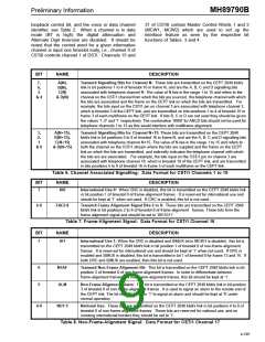
Channel 18 contains a Master Status Word 1
(MSW1) which provides to the user information
needed to determine the operating condition of the
CEPT interface, i.e., frame synchronization,
multiframe synchronization, frame alignment byte
errors, slips, alarms, and the logic of the external
status pin (see Table 14). Figure 11 shows the
relationship between the control stream channels,
and the CEPT signalling channels in the multiframe.
The ERR bit in the Master Status Word 1 is an
indicator of the number of errored frame alignment
bytes that have been received in alternate timeslot
zero. The time interval between toggles of the ERR
bit can be used to evaluate the bit error rate of the
line according to the CCITT Recommendation G.732
(see section on Frame Alignment Error Counter).
device on the line side may differ from the rate at
which it is being read out on the ST-BUS side.
When the clocks are not phase-locked, two
situations can occur:
Case #1: If the data on the line side is being written
in at a rate SLOWER than it is being read out on the
ST-BUS side, the distance between the write pointer
and the read pointer will begin to decrease over time.
When the distance is less than two channels, the
buffer will perform a controlled slip which will move
the read pointers to a new location 34 channels
away from the write pointer. This will result in the
REPETITION of the received frame.
Case #2: If the data on the line side is being written
in at a rate FASTER than it is being read out on the
ST-BUS side, the distance between the write pointer
and the read pointer will begin to increase over time.
When the distance exceeds 42 channels, the elastic
buffer will perform a controlled slip which will move
the read pointer to a new location ten channels away
from the write pointer. This will result in the LOSS of
the last received frame.
Channel 19 contains the Phase Status Word (see
Table 15) which can be used to determine the phase
relationship between the ST-BUS frame pulse (F0i)
and the rising edge of E8Ko. This information could
be used to determine the long term trend of the
received data rate, or to identify the direction of a
slip.
Channel 20 contains the CRC error count (see Table
16). This counter will wrap around once terminal
count is achieved (256 errors). If the maintenance
option is selected (bit 3 of MCW3) the counter is
reset once per second.
Note that when the device performs a controlled slip,
the ST-BUS address pointer is repositioned so that
there is either a 10 channel or 34 channel delay
between the input CEPT frame and the output
ST-BUS frame. Since the buffer performs
a
Channel 21 contains the Master Status Word 2 (see
Table 17). This byte identifies the status of the CRC
reframe and CRC sync. It also reports the Si bits
received in timeslot 0 of frames 13 and 15 and
controlled slip only if the delay exceeds 42 channels
or is less than two channels, there is a minimum
eight channel hysteresis built into the slip
mechanism. The device can, therefore, absorb eight
channels or 32.5µs of jitter in the received signal.
the ninth and most significant bit (b ) of the 9-bit
8
Phase Status Word.
There is no loss of frame synchronization, multiframe
synchronization or any errors in the signalling bits
when the device performs a slip.
Elastic Buffer
The MH89790B has a two frame elastic buffer at the
receiver which absorbs the jitter and wander in the
received signal. The received data is written into the
elastic buffer with the extracted E2o (2048 kHz)
clock and read out of the buffer on the ST-BUS side
with the system C2i (2048 kHz) clock (e.g., PBX
system clock). Under normal operating conditions,
in a synchronous network, the system C2i clock is
phase-locked to the extracted E2o clock. In this
situation every write operation to the elastic buffer is
followed by a read operation. Therefore, underflow
or overflow of data in the elastic buffer will not occur.
Frame Alignment Error Counter
The MH89790B provides an indication of the bit error
rate found on the link as required by CCITT
Recommendation G.703. The ERR bit (Bit 5 of
MSW1) is used to count the number of errors found
in the frame alignment signal and this can be used to
estimate the bit error rate. The ERR bit changes
state when 16 errors have been detected in the
frame alignment signal. This bit can not change state
more than once every 128 ms, placing an upper limit
-3
on the detectable error rate at approximately 10 .
The following formula can be used to calculate the
BER:
If the system clock is not phase-locked to the
extracted clock (e.g., lower quality link which is not
selected as the clock source for the PBX) then the
data rate at which the data is being written into the
4-199

 MITEL [ MITEL NETWORKS CORPORATION ]