MSP 34x7G
PRELIMINARY DATA SHEET
Contents
Page
Section
Title
5
6
6
7
1.
Introduction
1.1.
1.2.
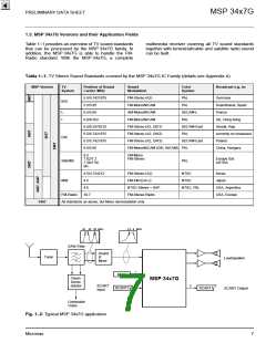
1.3.
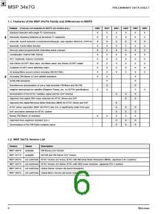
Features of the MSP 34x7G Family and Differences to MSPD
MSP 34x7G Version List
MSP 34x7G Versions and their Application Fields
8
2.
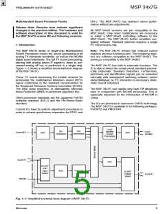
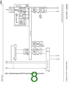
Functional Description
9
2.1.
Architecture of the MSP 34x7G Family
Sound IF Processing
9
2.2.
9
2.2.1.
2.2.2.
2.2.3.
2.2.4.
2.2.5.
2.3.
Analog Sound IF Input
9
Demodulator: Standards and Features
Preprocessing of Demodulator Signals
Automatic Sound Select
10
10
10
12
12
12
12
12
13
13
13
13
13
Manual Mode
Preprocessing for SCART
2.4.
Source Selection and Output Channel Matrix
Audio Baseband Processing
Automatic Volume Correction (AVC)
Quasi-Peak Detector
2.5.
2.5.1.
2.5.2.
2.6.
SCART Signal Routing
2.6.1.
2.6.2.
2.7.
SCART DSP In and SCART Out Select
Stand-by Mode
Digital Control I/O Pins and Status Change Indication
Clock PLL Oscillator and Crystal Specifications
2.8.
14
14
14
15
15
16
16
16
16
16
16
16
16
18
19
19
19
21
22
23
29
30
30
3.
Control Interface
3.1.
I2C Bus Interface
3.1.1.
3.1.2.
3.1.3.
3.1.4.
3.1.4.1.
3.1.4.2.
3.1.4.3.
3.1.4.4.
3.2.
Internal Hardware Error Handling
Description of CONTROL Register
Protocol Description
Proposals for General MSP 34x7G I2C Telegrams
Symbols
Write Telegrams
Read Telegrams
Examples
Start-Up Sequence: Power-Up and I2C-Controlling
MSP 34x7G Programming Interface
User Registers Overview
3.3.
3.3.1.
3.3.2.
3.3.2.1.
3.3.2.2.
3.3.2.3.
3.3.2.4.
3.3.2.5.
3.3.2.6.
3.3.2.7.
3.4.
Description of User Registers
STANDARD SELECT Register
Refresh of STANDARD SELECT Register
STANDARD RESULT Register
Write Registers on I2C Subaddress 10hex
Read Registers on I2C Subaddress 11hex
Write Registers on I2C Subaddress 12hex
Read Registers on I2C Subaddress 13hex
Programming Tips
3.5.
Examples of Minimum Initialization Codes
2
Micronas

 MICRONAS [ MICRONAS ]