NKE-XSC&NKE-XDC Series
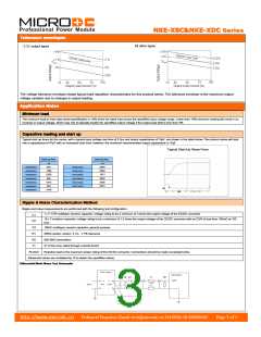
Tolerance envelopes
All other types
3.3V output types
The voltage tolerance envelope shows typical load regulation characteristics for this product series. The tolerance envelope is the maximum output
voltage variation due to changes in output loading.
Application Notes
Minimum load
The minimum load to meet data sheet speciffication is 10% of the full rated load across the speciffied input voltage range. Lower than 10% minimum loading will result in an
increase in output voltage, which may rise to typically double the speciffied output voltage if the output load falls to less than 5%.
Capacitive loading and start up
Typical start up times for this series, with a typical input voltage rise time of 2.2μs and output capacitance of 10μF, are shown in the table below. The product series will start
into a capacitance of 47μF with an increased start time, however, the maximum recommended output capacitance is 10μF.
Typical Start-Up Wave Form
Start-up time
μs
Start-up time
μs
NKE0303XSC
NKE0305XSC
NKE0309XSC
NKE0503XSC
NKE0505XSC
NKE0505XSEC
NKE0509XSC
544
NKE0512XSC
NKE0515XSC
NKE1205XSC
NKE1209XSC
NKE1212XSC
NKE1215XSC
5040
1306
5250
496
9940
1671
2835
1075
894
5295
8475
3140
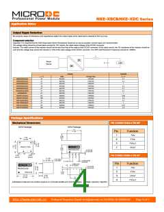
Ripple & Noise Characterization Method
Ripple and noise measurements are performed with the following test configuration.
1μF X7R multilayer ceramic capacitor, voltage rating to be a minimum of 3 times the output voltage of the DC/DC converter
C1
10μF tantalum capacitor, voltage rating to be a minimum of 1.5 times the output voltage of the DC/DC converter with an ESR of less than 100mΩ at 100
C2
kHz.
C3
R1
100nF multilayer ceramic capacitor, general purpose
450Ω resistor, carbon fi lm, ±1% tolerance
R2
50Ω BNC termination
T1
3T of the coax cable through a ferrite toroid
RLOAD
Resistive load to the maximum power rating of the DC/DC converter. Connections should be made via twisted wires
Measured values are multiplied by 10 to obtain the speciffied values.
Differential Mode Noise Test Schematic
http://www.microdc.cn
Technical Enquiries-Email:tech@microdc.cn Tel:0086-20-86000646
Page 3 of 5

 MICRODC [ MICRODC POWER TECHNOLOGY CO., LTD ]