NKE-XSC&NKE-XDC Series
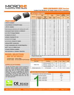
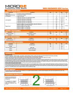
Output Specifications
Parameter
Conditions
TA=-40°C to 120°C,see derating graphs
Min.
Typ.
Max.
1.0
Units
W
Rated Power
Voltage Set Point Accuracy
Line regulation
See tolerance envelope
High Vin to low Vin
1.0
1.2
%%
%
10% load to rated load, 3.3V output types & 0309
10% load to rated load, 5V output types
10% load to rated load, 9V output types
10% load to rated load, 12V output types
10
12.8
7.5
1.2
15
Load regulation1
10
6.5
9.5
8.5
10% load to rated load, 15V output types
6.0
BW=DC to 20MHz, 3.3V output types,&0305, 0505XSEC,0505XDEC
BW=DC to 20MHz, other 5V output types
40
62
80
85
mV p-p
Ripple&Noise
BW=DC to 20MHz, 9V output types
BW=DC to 20MHz, 12V output types
BW=DC to 20MHz, 15V output types
103
49
170
75
39
65
Isolation Characteristics
Parameter
Conditions
Min.
3000
Typ.
10
Max.
Max.
Units
Isolation test voltage
resistance
Flash tested for 1 second
Viso= 1000VDC
VDC
GΩ
General Characteristics
Parameter
Conditions
Min.
Typ.
115
Units
kHz
Switching frequency
All output types
Temperature Characteristics
Parameter
Specification
Conditions
Min.
-40
Typ.
Max.
85
Units
All output types
Storage
Case temperature rise above
ambient
-50
130
41
℃
0505,1205
All other output types
32
Cooling
Free air convevtion
Technical notes
ISOLATION VOLTAGE
‘Hi Pot Test’, ‘Flash Tested’, ‘Withstand Voltage’, ‘Proof Voltage’, ‘Dielectric Withstand Voltage’ & ‘Isolation Test Voltage’ are all terms that relate to the same thing, a test voltage,
applied for a speciffied time, across a component designed to provide electrical isolation, to verify the integrity of that isolation.
MICRODC Power Module NKE series of dc/dc converters are all 100% production tested at their stated isolation voltage. This is 1000V DC for 1 second.
A question commonly asked is, “What is the continuous voltage that can be applied across the part in normal operation?”
The NKE series has been recognized by Underwriters Laboratory for functional insulation. Both input and output should normally be maintained within SELV limits.e.less than 42.4V peak, or 60VDC. The isolation
test voltage represents a measure of immunity to transient voltages and the part should never be used as an element of a safety isolation system. The part could be expected to function correctly with several
hundred volts offset applied continuously across the isolation barrier; but then the circuitry on both sides of the barrier must be regarded as operating at an unsafe voltage and further isolation/insulation systems
must form a barrier between these circuits and any user-accessible circuitry according to safety standard requirements.
REPEATED HIGH-VOLTAGE ISOLATION TESTING
It is well known that repeated high-voltage isolation testing of a barrier component can actually degrade isolation capability, to a lesser or greater degree depending on materi-als, construction and environment.
While manufactured parts can withstand several times the stated test voltage, the isolation capability does depend on the wire insulation. Any material, including this enamel (typically polyurethane) is susceptible
to eventual chemical degradation when subject to very high applied voltages thus implying that the number of tests should be strictly limited. We therefore strongly advise against repeated high voltage isolation
testing, but if it is absolutely required, that the voltage be reduced by 20% from speciffied test voltage.
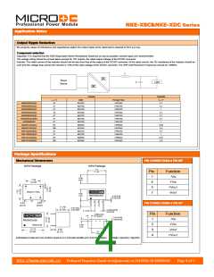
Safety Approval
The NKE series has been recognised by Underwriters Laboratory (UL) to UL 60950 for functional insulation in a maximum ambient temperature of 85ºC and/or case temperature limit of 130ºC. Case
temperature measured on the face opposite the pins.
Temperature derating graph
NKE0303XDC/XSC,0305XDC/XSC,030
All other types.
9XDC/XSC,0503XDC/XSC,0505XDEC/
XSEC types only.
UL recognition to a maximum
ambient temperature of 85ºC
and/or case temperature limit
of 130ºC.
http://www.microdc.cn
Technical Enquiries-Email:tech@microdc.cn Tel:0086-20-86000646
Page 2 of 5

 MICRODC [ MICRODC POWER TECHNOLOGY CO., LTD ]