TC620/TC621
Care must also be taken to ensure the LOW SET
temperature setting is at least 5°C lower than the HIGH
SET temperature setting.
3.0
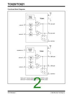
DETAILED DESCRIPTION
The TC620 has a positive temperature coefficient tem-
perature sensor and a dual threshold detector. Temper-
ature set point programming is accomplished with
external resistors from the HIGH SET and LOW SET
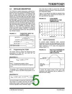
Figure 3-2 can help the user obtain an estimate of the
external resistor values required for the desired LOW
SET and HIGH SET trip points.
inputs to V
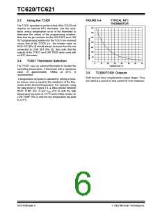
The HIGH LIMIT and LOW LIMIT outputs
DD.
remain low as long as measured temperature is below
set point values. As measured temperature increases,
the LOW LIMIT output is driven high when temperature
equals the LOW SET set point (±3°C max). If tempera-
ture continues to climb, the HIGH LIMIT output is driven
high when temperature equals the HIGH SET set point
(Figure 3-1). The CONTROL (hysteresis) output is
latched in its active state at the temperature specified
by the HIGH SET resistor. CONTROL is maintained
active until temperature falls to the value specified by
the LOW SET resistor.
FIGURE 3-2:
TC620 SENSE
RESISTORS VS. TRIP
TEMPERATURE
250
200
150
100
50
FIGURE 3-1:
TC620/TC621 INPUT VS.
OUTPUT LOGIC
-55
-35
-15
5
25
45
65
85
105
125
TEMPERATURE (˚C)
High Set Point
Temperature
Low Set Point
Low Limit Output
High Limit Output
3.2
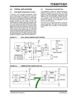
Built-in Hysteresis
To prevent output "chattering" when measured
temperature is at (or near) the programmed trip point
values, the LOW SET and HIGH SET inputs each have
built-in hysteresis of -2°C below the programmed
settings (Figure 3-3).
Control Output (Cool Option
Control Output (Heat Option)
3.1
Programming the TC620
FIGURE 3-3:
BUILT-IN HYSTERESIS ON
LOW LIMIT AND HIGH
LIMIT OUTPUTS
The resistor values to achieve the desired trip point
temperatures on HIGH SET and LOW SET are
calculated using Equation 3-1:
EQUATION 3-1:
Set Point
(Set Point 2˚C)
2.1312
R
= 0.5997 x T
TRIP
Where:
R
= Programming resistor in Ohms
TRIP
High Limit
or Low Limit
Output
T = The desired trip point temperature in degrees
Kelvin.
For example, a 50°C setting on either the HIGH SET
or LOW SET input is calculated using Equation 3-2 as
follows:
As shown, the outputs remain in their active state
(hysteresis) until temperature falls an additional 2°C
below the user's setting.
EQUATION 3-2:
2.1312
R
= 0.5997 x ((50 + 273.15)
) = 133.6kΩ
SET
Care must be taken to ensure the LOW SET program-
ming resistor is a smaller value than the HIGH SET
programming resistor. Failure to do this will result in
erroneous operation of the CONTROL output.
2002 Microchip Technology Inc.
DS21439B-page 5

 MICROCHIP [ MICROCHIP ]