PIC24FJ64GA104 FAMILY
19.4.1
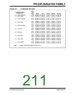
CONFIGURING THE ALARM
19.3 Calibration
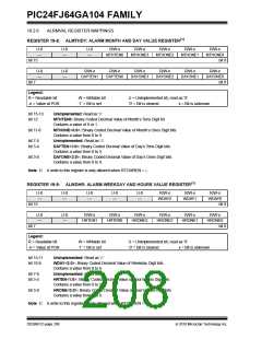
The alarm feature is enabled using the ALRMEN bit.
This bit is cleared when an alarm is issued. Writes to
ALRMVAL should only take place when ALRMEN = 0.
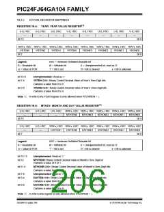
The real-time crystal input can be calibrated using the
periodic auto-adjust feature. When properly calibrated,
the RTCC can provide an error of less than 3 seconds
per month. This is accomplished by finding the number
of error clock pulses and storing the value into the
lower half of the RCFGCAL register. The 8-bit signed
value loaded into the lower half of RCFGCAL is
multiplied by four and will either be added or subtracted
from the RTCC timer, once every minute. Refer to the
steps below for RTCC calibration:
As displayed in Figure 19-2, the interval selection of the
alarm is configured through the AMASK bits
(ALCFGRPT<13:10>). These bits determine which and
how many digits of the alarm must match the clock
value for the alarm to occur.
The alarm can also be configured to repeat based on a
preconfigured interval. The amount of times this
occurs, once the alarm is enabled, is stored in the
ARPT<7:0> bits (ALCFGRPT<7:0>). When the value
of the ARPT bits equals 00h and the CHIME bit
(ALCFGRPT<14>) is cleared, the repeat function is
disabled and only a single alarm will occur. The alarm
can be repeated up to 255 times by loading
ARPT<7:0> with FFh.
1. Using another timer resource on the device; the
user must find the error of the 32.768 kHz crystal.
2. Once the error is known, it must be converted to
the number of error clock pulses per minute.
3. a) If the oscillator is faster than ideal (negative
result from step 2), the RCFGCAL register value
must be negative. This causes the specified
number of clock pulses to be subtracted from
the timer counter, once every minute.
After each alarm is issued, the value of the ARPT bits
is decremented by one. Once the value has reached
00h, the alarm will be issued one last time, after which,
the ALRMEN bit will be cleared automatically and the
alarm will turn off.
b) If the oscillator is slower than ideal (positive
result from step 2), the RCFGCAL register value
must be positive. This causes the specified
number of clock pulses to be subtracted from
the timer counter, once every minute.
Indefinite repetition of the alarm can occur if the
CHIME bit = 1. Instead of the alarm being disabled
when the value of the ARPT bits reaches 00h, it rolls
over to FFh and continues counting indefinitely while
CHIME is set.
Divide the number of error clocks per minute by 4 to get
the correct calibration value and load the RCFGCAL
register with the correct value. (Each 1-bit increment in
the calibration adds or subtracts 4 pulses.)
19.4.2
ALARM INTERRUPT
EQUATION 19-1:
At every alarm event, an interrupt is generated. In
addition, an alarm pulse output is provided that
operates at half the frequency of the alarm. This output
is completely synchronous to the RTCC clock and can
be used as a trigger clock to other peripherals.
(Ideal Frequency† – Measured Frequency) * 60 =
Clocks per Minute
† Ideal Frequency = 32,768 Hz
Note:
Changing any of the registers, other than
the RCFGCAL and ALCFGRPT registers,
and the CHIME bit while the alarm is
enabled (ALRMEN = 1), can result in a
false alarm event leading to a false alarm
interrupt. To avoid a false alarm event, the
timer and alarm values should only be
changed while the alarm is disabled
(ALRMEN = 0). It is recommended that the
ALCFGRPT register and CHIME bit be
changed when RTCSYNC = 0.
Writes to the lower half of the RCFGCAL register
should only occur when the timer is turned off or
immediately after the rising edge of the seconds pulse.
Note:
It is up to the user to include, in the error
value, the initial error of the crystal drift
due to temperature and drift due to crystal
aging.
19.4 Alarm
• Configurable from half second to one year
• Enabled using the ALRMEN bit (ALCFGRPT<15>)
• One-time alarm and repeat alarm options are
available
DS39951C-page 210
2010 Microchip Technology Inc.

 MICROCHIP [ MICROCHIP ]