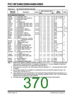
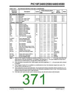
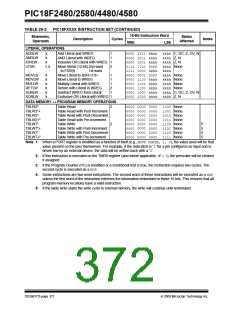
PIC18F2480/2580/4480/4580
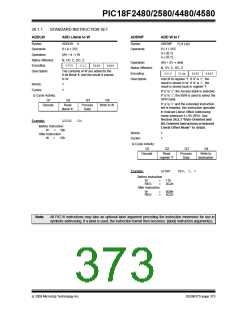
ADDWFC
ADD W and Carry bit to f
ANDLW
AND Literal with W
Syntax:
ADDWFC
f {,d {,a}}
Syntax:
ANDLW
k
Operands:
0 ≤ f ≤ 255
d ∈ [0,1]
a ∈ [0,1]
Operands:
Operation:
Status Affected:
Encoding:
Description:
0 ≤ k ≤ 255
(W) .AND. k → W
N, Z
Operation:
(W) + (f) + (C) → dest
0000
1011
kkkk
kkkk
Status Affected:
Encoding:
N,OV, C, DC, Z
The contents of W are ANDed with the
8-bit literal ‘k’. The result is placed in W.
0010
00da
ffff
ffff
Description:
Add W, the Carry flag and data memory
location ‘f’. If ‘d’ is ‘0’, the result is
placed in W. If ‘d’ is ‘1’, the result is
placed in data memory
Words:
1
1
Cycles:
Q Cycle Activity:
Q1
location ‘f’.
Q2
Q3
Q4
If ‘a’ is ‘0’, the Access Bank is selected.
If ‘a’ is ‘1’, the BSR is used to select the
GPR bank.
Decode
Read literal
‘k’
Process
Data
Write to W
If ‘a’ is ‘0’ and the extended instruction
set is enabled, this instruction operates
in Indexed Literal Offset Addressing
mode whenever f ≤ 95 (5Fh). See
Section 26.2.3 “Byte-Oriented and
Bit-Oriented Instructions in Indexed
Literal Offset Mode” for details.
Example:
ANDLW
05Fh
Before Instruction
W
=
A3h
03h
After Instruction
W
=
Words:
Cycles:
1
1
Q Cycle Activity:
Q1
Q2
Q3
Q4
Decode
Read
register ‘f’
Process
Data
Write to
destination
Example:
ADDWFC
REG, 0, 1
Before Instruction
Carry bit =
1
02h
4Dh
REG
W
=
=
After Instruction
Carry bit =
0
02h
50h
REG
W
=
=
DS39637D-page 374
© 2009 Microchip Technology Inc.

 MICROCHIP [ MICROCHIP ]