PIC18F2480/2580/4480/4580
If the general call address matches, the SSPSR is
transferred to the SSPBUF, the BF flag bit is set (eighth
bit), and on the falling edge of the ninth bit (ACK bit),
the SSPIF interrupt flag bit is set.
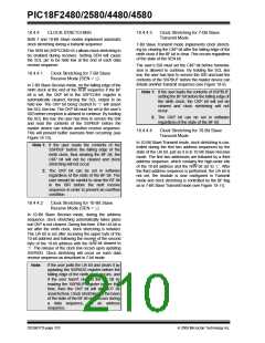
18.4.5
GENERAL CALL ADDRESS
SUPPORT
The addressing procedure for the I2C bus is such that
the first byte after the Start condition usually deter-
mines which device will be the slave addressed by the
master. The exception is the general call address which
can address all devices. When this address is used, all
devices should, in theory, respond with an
Acknowledge.
When the interrupt is serviced, the source for the
interrupt can be checked by reading the contents of the
SSPBUF. The value can be used to determine if the
address was device-specific or a general call address.
In 10-bit mode, the SSPADD is required to be updated
for the second half of the address to match and the UA
bit is set (SSPSTAT<1>). If the general call address is
sampled when the GCEN bit is set, while the slave is
configured in 10-Bit Addressing mode, then the second
half of the address is not necessary, the UA bit will not
be set and the slave will begin receiving data after the
Acknowledge (Figure 18-15).
The general call address is one of eight addresses
reserved for specific purposes by the I2C protocol. It
consists of all ‘0’s with R/W = 0.
The general call address is recognized when the
General Call Enable bit (GCEN) is enabled
(SSPCON2<7> set). Following a Start bit detect, 8 bits
are shifted into the SSPSR and the address is
compared against the SSPADD. It is also compared to
the general call address and fixed in hardware.
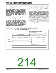
FIGURE 18-15:
SLAVE MODE GENERAL CALL ADDRESS SEQUENCE
(7 OR 10-BIT ADDRESSING MODE)
Address is compared to General Call Address
after ACK, set interrupt
Receiving Data
D5 D4 D3 D2 D1
ACK
R/W = 0
General Call Address
ACK
SDA
SCL
D7 D6
D0
8
1
2
3
4
5
6
7
8
9
1
2
3
4
5
6
7
9
S
SSPIF
BF (SSPSTAT<0>)
Cleared in software
SSPBUF is read
SSPOV (SSPCON1<6>)
GCEN (SSPCON2<7>)
‘0’
‘1’
DS39637D-page 214
© 2009 Microchip Technology Inc.

 MICROCHIP [ MICROCHIP ]