PIC18F6525/6621/8525/8621
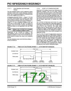
8. If auto-restart operation is required, set the
P1RSEN bit (ECCP1DEL<7>).
17.4.9
SETUP FOR PWM OPERATION
The following steps should be taken when configuring
the ECCP1 module for PWM operation using Timer2:
9. Configure and start TMR2:
• Clear the TMR2 interrupt flag bit by clearing
the TMR2IF bit (PIR1<1>).
1. Configure the PWM pins, P1A and P1B (and
P1C and P1D, if used), as inputs by setting the
corresponding TRIS bits.
• Set the TMR2 prescale value by loading the
T2CKPS bits (T2CON<1:0>).
2. Set the PWM period by loading the PR2 register.
3. If auto-shutdown is required do the following:
• Disable auto-shutdown (ECCP1AS = 0)
• Enable Timer2 by setting the TMR2ON bit
(T2CON<2>).
10. Enable PWM outputs after a new PWM cycle
has started:
• Configure source (FLT0, Comparator 1 or
Comparator 2)
• Wait until TMRn overflows (TMRnIF bit is set).
• Wait for non-shutdown condition
• Enable the ECCP1/P1A, P1B, P1C and/or
P1D pin outputs by clearing the respective
TRIS bits.
4. Configure the ECCP1 module for the desired
PWM mode and configuration by loading the
CCP1CON register with the appropriate values:
• Clear the ECCP1ASE bit (ECCP1AS<7>).
• Select one of the available output
configurations and direction with the
P1M1:P1M0 bits.
17.4.10 EFFECTS OF A RESET
Both Power-on Reset and subsequent Resets will force
all ports to Input mode and the CCP registers to their
Reset states.
• Select the polarities of the PWM output
signals with the CCP1M3:CCP1M0 bits.
5. Set the PWM duty cycle by loading the CCPR1L
register and CCP1CON<5:4> bits.
This forces the Enhanced CCP module to reset to a
state compatible with the standard CCP module.
6. For Half-Bridge Output mode, set the
dead-band delay by loading ECCP1DEL<6:0>
with the appropriate value.
7. If auto-shutdown operation is required, load the
ECCP1AS register:
• Select the auto-shutdown sources using the
ECCP1AS2:ECCP1AS0 bits.
• Select the shutdown states of the PWM
output pins using the PSS1AC1:PSS1AC0
and PSS1BD1:PSS1BD0 bits.
• Set the ECCP1ASE bit (ECCP1AS<7>).
• Configure the comparators using the CMCON
register.
• Configure the comparator inputs as analog
inputs.
2005 Microchip Technology Inc.
DS39612B-page 171

 MICROCHIP [ MICROCHIP ]