PIC17C75X
VTH (Input Threshold Voltage) of OSC1
F
Input (In XT, HS, and LP Modes) vs. VDD ................ 259
WDT Timer Time-Out Period vs. VDD....................... 256
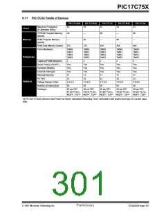
Family of Devices
PIC12CXXX .............................................................. 293
H
PIC14C000 ............................................................... 293
PIC16C15X............................................................... 294
PIC16C55X............................................................... 296
PIC16C5X................................................................. 295
PIC16C62X and PIC16C64X.................................... 296
PIC16C6X................................................................. 297
PIC16C7XX............................................................... 298
PIC16C8X................................................................. 299
PIC16C9XX............................................................... 300
PIC17C75X................................................................... 6
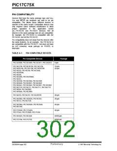
PIC17CXX................................................................. 301
FERR ................................................................................ 115
Flowcharts
Acknowledge............................................................. 156
Master Receiver........................................................ 153
Master Transmit........................................................ 150
Restart Condition ...................................................... 147
Start Condition .......................................................... 145
Stop Condition .......................................................... 158
FOSC0.............................................................................. 177
FOSC1.............................................................................. 177
FS0 ............................................................................. 47, 274
FS1 ............................................................................. 47, 274
FS2 ............................................................................. 47, 274
FS3 ............................................................................. 47, 274
FSR0............................................................................. 44, 51
FSR1............................................................................. 44, 51
Fuzzy Logic Dev. System (fuzzyTECH -MP) .......... 219, 221
G
GCE .................................................................................. 126
General Call Address Sequence....................................... 139
General Call Address Support .......................................... 139
General Call Enable bit, GCE ........................................... 126
General Format for Instructions ........................................ 184
General Purpose RAM........................................................ 39
General Purpose RAM Bank............................................... 53
General Purpose Register (GPR) ....................................... 42
GLINTD......................................................... 35, 48, 101, 180
Global Interrupt Disable bit, GLINTD .................................. 35
GOTO ............................................................................... 198
GPR (General Purpose Register) ....................................... 42
GPR Banks ......................................................................... 53
Graphs
Hardware Multiplier..............................................................61
I
I/O Ports
Bi-directional................................................................83
I/O Ports ......................................................................65
Programming Considerations......................................83
Read-Modify-Write Instructions ...................................83
Successive Operations................................................83
2
I C .................................................................................... 134
2
Addressing I C Devices............................................ 268
Arbitration ................................................................. 270
Combined Format..................................................... 269
2
I C Overview ............................................................ 267
Initiating and Terminating Data Transfer .................. 267
Master-Receiver Sequence...................................... 269
Master-Transmitter Sequence.................................. 269
Multi-master.............................................................. 270
START...................................................................... 267
STOP................................................................ 267, 268
Transfer Acknowledge.............................................. 268
2
I C Master Mode Receiver Flowchart............................... 153
2
I C Master Mode Reception ............................................. 152
2
I C Master Mode Restart Condition.................................. 146
2
I C Mode Selection........................................................... 134
2
I C Module
Acknowledge Flowchart............................................ 156
Acknowledge Sequence timing ................................ 155
Addressing................................................................ 135
Baud Rate Generator ............................................... 143
Block Diagram .......................................................... 141
BRG Block Diagram ................................................. 143
BRG Reset due to SDA Collision ............................. 162
BRG Timing.............................................................. 143
Bus Arbitration.......................................................... 160
Bus Collision............................................................. 160
Acknowledge.................................................... 160
Restart Condition.............................................. 163
Restart Condition Timing (Case1).................... 163
Restart Condition Timing (Case2).................... 163
Start Condition.................................................. 161
Start Condition Timing.............................. 161, 162
Stop Condition.................................................. 164
Stop Condition Timing (Case1) ........................ 164
Stop Condition Timing (Case2) ........................ 164
Transmit Timing................................................ 160
Bus Collision timing .................................................. 160
Clock Arbitration ....................................................... 159
Clock Arbitration Timing (Master Transmit).............. 159
Conditions to not give ACK Pulse............................. 135
General Call Address Support.................................. 139
Master Mode............................................................. 141
Master Mode 7-bit Reception timing......................... 154
Master Mode Operation............................................ 142
Master Mode Start Condition.................................... 144
Master Mode Transmission ...................................... 149
Master Mode Transmit Sequence ............................ 142
Master Transmit Flowchart....................................... 150
Multi-Master Communication.................................... 160
Multi-master Mode.................................................... 142
Operation.................................................................. 134
Repeat Start Condition timing................................... 146
Restart Condition Flowchart ..................................... 147
Slave Mode............................................................... 135
IOH vs. VOH, VDD = 3V .............................................. 256
IOH vs. VOH, VDD = 5V .............................................. 257
IOL vs. VOL, VDD = 3V ............................................... 257
IOL vs. VOL, VDD = 5V ............................................... 258
Maximum IDD vs. Frequency (External Clock
125°C to -40°C) ........................................................ 253
Maximum IPD vs. VDD Watchdog Disabled............... 254
Maximum IPD vs. VDD Watchdog Enabled................ 255
RC Oscillator Frequency vs. VDD (Cext = 100 pF).... 250
RC Oscillator Frequency vs. VDD (Cext = 22 pF)...... 250
RC Oscillator Frequency vs. VDD (Cext = 300 pF).... 251
Transconductance of LF Oscillator vs.VDD ............... 252
Transconductance of XT Oscillator vs. VDD.............. 252
Typical IDD vs. Frequency (External Clock 25°C) ..... 253
Typical IPD vs. VDD Watchdog Disabled 25°C .......... 254
Typical IPD vs. VDD Watchdog Enabled 25°C........... 255
Typical RC Oscillator vs. Temperature ..................... 249
VIH, VIL of MCLR, T0CKI and OSC1 (In RC Mode)
vs. VDD...................................................................... 259
VTH (Input Threshold Voltage) of I/O Pins vs. VDD ... 258
1997 Microchip Technology Inc.
Preliminary
DS30264A-page 305

 MICROCHIP [ MICROCHIP ]