PIC17C75X
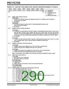
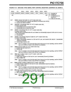
FIGURE F-19: SSPCON2: SYNC SERIAL PORT CONTROL REGISTER2 (ADDRESS 12h, BANK 6)
R/W-0
R-0
R/W-0
R/W-0
R/W-0
R/W-0
PEN
R/W-0 R/W-0
RSEN SEN
bit0
GCEN ACKSTAT ACKDT ACKEN RCEN
bit7
R =Readable bit
W = Writable bit
U =Unimplemented bit,
Read as ‘0’
- n =Value at POR reset
bit 7:
bit 6:
GCEN: General Call Enable bit (In I2C slave mode only)
1 = Enable interrupt when a general call address is received in the SSPSR.
0 = General call address disabled.
ACKSTAT: Acknowledge Status bit (In I2C master mode only)
In master transmit mode:
1 = Acknowledge was not received from slave
0 = Acknowledge was received from slave
bit 5:
bit 4:
ACKDT: Acknowledge Data bit (In I2C master mode only)
In master receive mode:
Value that will be transmitted when the user initiates an Acknowledge sequence at the end of a receive.
1 = Not Acknowledge
0 = Acknowledge
ACKEN: Acknowledge Sequence Enable bit (In I2C master mode only).
In master receive mode:
1 = Initiate Acknowledge sequence on SDA and SCL pins, and transmit AKD data bit. Automatically
cleared by hardware.
0 = Acknowledge sequence idle
2
Note: If the I C module is not in the idle mode, this bit may not be set (no spooling), and the SSPBUF
may not be written (or writes to the SSPBUF are disabled).
bit 3:
RCEN: Receive enable bit (In I2C master mode only).
1 = Enables Receive mode for I2C
0 = Receive idle
2
Note: If the I C module is not in the idle mode, this bit may not be set (no spooling), and the SSPBUF
may not be written (or writes to the SSPBUF are disabled).
bit 2:
PEN: Stop Condition Enable bit (In I2C master mode only).
SCK release control
1 = Initiate Stop condition on SDA and SCL pins. Automatically cleared by hardware.
0 = Stop condition idle
2
Note: If the I C module is not in the idle mode, this bit may not be set (no spooling), and the SSPBUF
may not be written (or writes to the SSPBUF are disabled).
bit 1: RSEN: Restart Condition Enabled bit (In I2C master mode only)
1 = Initiate Restart condition on SDA and SCL pins. Automatically cleared by hardware.
0 = Restart condition idle.
2
Note: If the I C module is not in the idle mode, this bit may not be set (no spooling), and the SSPBUF
may not be written (or writes to the SSPBUF are disabled)
bit 0: SEN: Start Condition Enabled bit (In I2C master mode only)
1 = Initiate Start condition on SDA and SCL pins. Automatically cleared by hardware.
0 = Start condition idle.
2
Note: If the I C module is not in the idle mode, this bit may not be set (no spooling), and the SSPBUF
may not be written (or writes to the SSPBUF are disabled)
1997 Microchip Technology Inc.
Preliminary
DS30264A-page 291

 MICROCHIP [ MICROCHIP ]