PIC17C75X
8.1.1
TERMINATING LONG WRITES
8.1
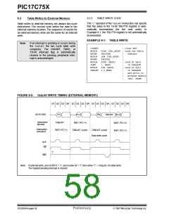
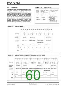
Table Writes to Internal Memory
An interrupt source or reset are the only events that
terminate a long write operation. Terminating the long
write from an interrupt source requires that the inter-
rupt enable and flag bits are set. The GLINTD bit only
enables the vectoring to the interrupt address.
A table write operation to internal memory causes a
long write operation. The long write is necessary for
programming the internal EPROM. Instruction execu-
tion is halted while in a long write cycle. The long write
will be terminated by any enabled interrupt. To ensure
that the EPROM location has been well programmed,
a minimum programming time is required (see specifi-
cation #D114). Having only one interrupt enabled to
terminate the long write ensures that no unintentional
interrupts will prematurely terminate the long write.
If the T0CKI, RA0/INT, or TMR0 interrupt source is
used to terminate the long write; the interrupt flag, of
the highest priority enabled interrupt, will terminate the
long write and automatically be cleared.
The sequence of events for programming an internal
program memory location should be:
Note 1: If an interrupt is pending, the TABLWTis
aborted (an NOP is executed). The
highest priority pending interrupt, from
the T0CKI, RA0/INT, or TMR0 sources
that is enabled, has its flag cleared.
1. Disable all interrupt sources, except the source
to terminate EPROM program write.
2. Raise MCLR/VPP pin to the programming volt-
age.
Note 2: If the interrupt is not being used for the
program write timing, the interrupt
should be disabled. This will ensure that
the interrupt is not lost, nor will it termi-
nate the long write prematurely.
3. Clear the WDT.
4. Do the table write. The interrupt will terminate
the long write.
5. Verify the memory location (table read).
If a peripheral interrupt source is used to terminate the
long write, the interrupt enable and flag bits must be
set. The interrupt flag will not be automatically cleared
upon the vectoring to the interrupt vector address.
Note 1: Programming requirements must be
met. See timing specification in electrical
specifications for the desired device.
Violating these specifications (including
temperature) may result in EPROM
locations that are not fully programmed
and may lose their state over time.
The GLINTD bit determines whether the program will
branch to the interrupt vector when the long write is
terminated. If GLINTD is clear, the program will vector,
if GLINTD is set, the program will not vector to the
interrupt address.
Note 2: If the VPP requirement is not met, the
table write is a 2 cycle write and the pro-
gram memory is unchanged.
TABLE 8-1:
INTERRUPT - TABLE WRITE INTERACTION
Interrupt
Source
Enable
Bit
Flag
Bit
GLINTD
Action
RA0/INT, TMR0,
T0CKI
0
1
1
Terminate long table write (to internal program
memory), branch to interrupt vector (branch clears
flag bit).
0
1
1
1
0
1
0
x
1
None
None
Terminate table write, do not branch to interrupt
vector (flag is automatically cleared).
Peripheral
0
0
1
1
1
1
0
1
1
0
x
1
Terminate table write, branch to interrupt vector.
None
None
Terminate table write, do not branch to interrupt
vector (flag remains set).
1997 Microchip Technology Inc.
Preliminary
DS30264A-page 57

 MICROCHIP [ MICROCHIP ]