PIC16F917/916/914/913
RG Pins.......................................................................85
SSP (I C Mode) ........................................................202
Assigning Prescaler to WDT..................................... 100
Call of a Subroutine in Page 1 from Page 0 ............... 40
Changing Between Capture Prescalers.................... 213
Indirect Addressing..................................................... 41
Initializing PORTA....................................................... 44
Initializing PORTB....................................................... 53
Initializing PORTC ...................................................... 62
Initializing PORTD ...................................................... 71
Initializing PORTE....................................................... 76
Initializing PORTF....................................................... 81
Initializing PORTG ...................................................... 84
Loading the SSPBUF (SSPSR) Register.................. 196
Saving Status and W Registers in RAM ................... 233
Code Protection................................................................ 238
Comparator....................................................................... 109
C2OUT as T1 Gate................................................... 117
Configurations .......................................................... 112
Interrupts .................................................................. 114
Operation.......................................................... 109, 114
Operation During Sleep ............................................ 115
Response Time......................................................... 114
Synchronizing COUT w/Timer1 ................................ 117
Comparator Module
2
SSP (SPI Mode)........................................................193
Timer1.......................................................................102
Timer2.......................................................................107
TMR0/WDT Prescaler.................................................99
Watchdog Timer (WDT)............................................234
Brown-out Reset (BOR) ....................................................223
Associated Registers ................................................224
Calibration.................................................................223
Specifications............................................................269
Timing and Characteristics .......................................268
C
C Compilers
MPLAB C18 ..............................................................252
MPLAB C30 ..............................................................252
Capture Module. See Capture/Compare/PWM (CCP)
Capture/Compare/PWM (CCP).........................................211
Associated registers w/ Capture/Compare/PWM......218
Capture Mode ...........................................................213
CCPx Pin Configuration ............................................213
Compare Mode .........................................................214
CCPx Pin Configuration....................................214
Software Interrupt Mode ........................... 213, 214
Special Event Trigger........................................214
Timer1 Mode Selection............................. 213, 214
Interaction of Two CCP Modules (table) ...................211
Prescaler...................................................................213
PWM Mode ...............................................................215
Duty Cycle.........................................................216
Effects of Reset.................................................218
Example PWM Frequencies and
Associated registers ................................................. 119
Comparator Voltage Reference (CVREF)
Response Time......................................................... 114
Comparator Voltage Reference (CVREF).......................... 118
Effects of a Reset ..................................................... 115
Specifications ........................................................... 271
Comparators
C2OUT as T1 Gate................................................... 103
Effects of a Reset ..................................................... 115
Specifications ........................................................... 271
Compare Module. See Capture/Compare/PWM (CCP)
CONFIG1 Register ........................................................... 220
Configuration Bits ............................................................. 220
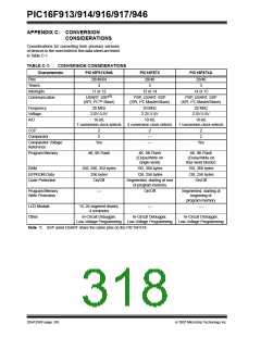
Conversion Considerations............................................... 316
CPU Features................................................................... 219
Customer Change Notification Service............................. 325
Customer Notification Service .......................................... 325
Customer Support............................................................. 325
Resolutions, 20 MHZ ................................217
Example PWM Frequencies and
Resolutions, 8 MHz...................................217
Operation in Sleep Mode ..................................218
Setup for Operation...........................................218
System Clock Frequency Changes...................218
PWM Period..............................................................216
Setup for PWM Operation.........................................218
Timer Resources.......................................................211
CCP. See Capture/Compare/PWM (CCP)
D
CCPxCON Register ..........................................................212
CKE bit..............................................................................194
CKP bit..............................................................................195
Clock Sources
D/A bit............................................................................... 194
Data EEPROM Memory.................................................... 187
Associated Registers................................................ 192
Reading .................................................................... 190
Writing ...................................................................... 190
Data Memory ...................................................................... 24
Data/Address bit (D/A)...................................................... 194
DC and AC Characteristics
Graphs and Tables ................................................... 283
DC Characteristics
Extended and Industrial............................................ 261
Industrial and Extended............................................ 257
Development Support....................................................... 251
Device Overview................................................................. 15
External Modes...........................................................89
EC.......................................................................89
HS.......................................................................90
LP........................................................................90
OST.....................................................................89
RC.......................................................................91
XT .......................................................................90
Internal Modes ............................................................91
Frequency Selection ...........................................93
HFINTOSC..........................................................91
INTOSC ..............................................................91
INTOSCIO...........................................................91
LFINTOSC ..........................................................93
Clock Switching...................................................................95
CMCON0 Register ............................................................116
CMCON1 Register ............................................................117
Code Examples
E
EEADRH Registers................................................... 187, 188
EEADRL Register............................................................. 188
EEADRL Registers ........................................................... 187
EECON1 Register..................................................... 187, 189
EECON2 Register............................................................. 187
EEDATH Register............................................................. 188
EEDATL Register ............................................................. 188
A/D Conversion.........................................................179
Assigning Prescaler to Timer0 ..................................100
DS41250F-page 318
© 2007 Microchip Technology Inc.

 MICROCHIP [ MICROCHIP ]