PIC16F913/914/916/917/946
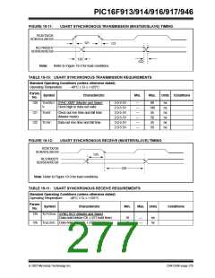
FIGURE 19-11:
USART SYNCHRONOUS TRANSMISSION (MASTER/SLAVE) TIMING
RC6/TX/CK
SCK/SCL/SEG9
121
121
RC7/RX/DT/
SDI/SDA/SEG8
120
Refer to Figure 19-3 for load conditions.
122
Note:
TABLE 19-10: USART SYNCHRONOUS TRANSMISSION REQUIREMENTS
Standard Operating Conditions (unless otherwise stated)
Operating Temperature
-40°C ≤ TA ≤ +125°C
Param.
Symbol
No.
Characteristic
Min.
Max.
Units Conditions
120
121
122
TCKH2DT SYNC XMIT (Master and Slave)
3.0-5.5V
2.0-5.5V
3.0-5.5V
2.0-5.5V
3.0-5.5V
2.0-5.5V
—
—
—
—
—
—
80
100
45
ns
ns
ns
ns
ns
ns
V
Clock high to data-out valid
TCKRF
Clock out rise time and fall time
(Master mode)
50
TDTRF
Data-out rise time and fall time
45
50
FIGURE 19-12:
RC6/TX/CK
USART SYNCHRONOUS RECEIVE (MASTER/SLAVE) TIMING
SCK/SCL/SEG9
125
RC7/RX/DT/
SDI/SDA/SEG8
126
Note: Refer to Figure 19-3 for load conditions.
TABLE 19-11: USART SYNCHRONOUS RECEIVE REQUIREMENTS
Standard Operating Conditions (unless otherwise stated)
Operating Temperature
-40°C ≤ TA ≤ +125°C
Param.
Symbol
No.
Characteristic
Min.
Max. Units
Conditions
125
TDTV2CKL SYNC RCV (Master and Slave)
Data-hold before CK ↓ (DT hold time)
TCKL2DTL Data-hold after CK ↓ (DT hold time)
10
15
—
—
ns
ns
126
© 2007 Microchip Technology Inc.
DS41250F-page 275

 MICROCHIP [ MICROCHIP ]