PIC16F913/914/916/917/946
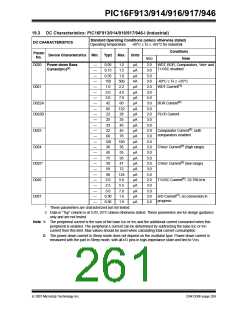
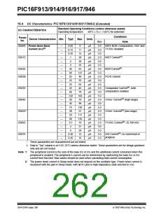
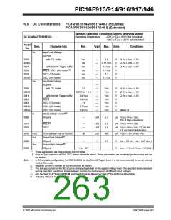
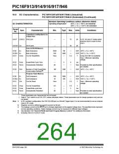
19.3 DC Characteristics: PIC16F913/914/916/917/946-I (Industrial)
Standard Operating Conditions (unless otherwise stated)
Operating temperature -40°C ≤ TA ≤ +85°C for industrial
DC CHARACTERISTICS
Conditions
Param
No.
Device Characteristics Min.
Typ†
Max.
Units
VDD
Note
D020
Power-down Base
Current(IPD)(2)
—
—
—
—
—
—
—
—
—
—
—
—
—
—
—
—
—
—
—
—
—
—
—
—
—
—
0.05
0.15
0.35
150
1.0
2.0
3.0
42
1.2
1.5
1.8
500
2.2
4.0
7.0
60
μA
μA
μA
nA
μA
μA
μA
μA
μA
μA
μA
μA
μA
μA
μA
μA
μA
μA
μA
μA
μA
μA
μA
μA
μA
μA
2.0
3.0
5.0
3.0
2.0
3.0
5.0
3.0
5.0
2.0
3.0
5.0
2.0
3.0
5.0
2.0
3.0
5.0
2.0
3.0
5.0
2.0
3.0
5.0
3.0
5.0
WDT, BOR, Comparators, VREF and
T1OSC disabled
-40°C ≤ TA ≤ +25°C
WDT Current(1)
D021
D022A
D022B
BOR Current(1)
PLVD Current
85
122
28
22
25
35
33
45
D023
D024
D025*
D026
D027
32
45
Comparator Current(1), both
comparators enabled
60
78
120
30
160
36
CVREF Current(1) (high range)
CVREF Current(1) (low range)
T1OSC Current(1), 32.768 kHz
45
55
75
95
39
47
59
72
98
124
5.0
5.5
7.0
1.6
1.9
2.0
2.5
3.0
0.30
0.36
A/D Current(1), no conversion in
progress
*
These parameters are characterized but not tested.
†
Data in “Typ” column is at 5.0V, 25°C unless otherwise stated. These parameters are for design guidance
only and are not tested.
Note 1: The peripheral current is the sum of the base IDD or IPD and the additional current consumed when this
peripheral is enabled. The peripheral Δ current can be determined by subtracting the base IDD or IPD
current from this limit. Max values should be used when calculating total current consumption.
2: The power-down current in Sleep mode does not depend on the oscillator type. Power-down current is
measured with the part in Sleep mode, with all I/O pins in high-impedance state and tied to VDD.
© 2007 Microchip Technology Inc.
DS41250F-page 259

 MICROCHIP [ MICROCHIP ]