PIC16F87/88
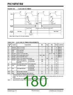
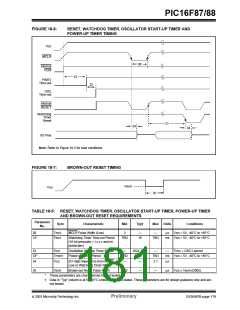
FIGURE 18-6:
RESET, WATCHDOG TIMER, OSCILLATOR START-UP TIMER AND
POWER-UP TIMER TIMING
VDD
MCLR
30
Internal
POR
33
PWRT
Time-out
32
OSC
Time-out
Internal
RESET
Watchdog
Timer
Reset
31
34
34
I/O Pins
Note: Refer to Figure 18-3 for load conditions.
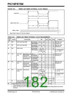
FIGURE 18-7:
BROWN-OUT RESET TIMING
VBOR
VDD
35
TABLE 18-5: RESET, WATCHDOG TIMER, OSCILLATOR START-UP TIMER, POWER-UP TIMER
AND BROWN-OUT RESET REQUIREMENTS
Parameter
Sym
Characteristic
Min
Typ†
Max
Units
Conditions
No.
30
TmcL
MCLR Pulse Width (Low)
2
—
—
µs
VDD = 5V, -40°C to +85°C
31*
TWDT
Watchdog Timer Time-out Period
(16-bit prescaler = 0100and no
postscaler)
TBD
16
TBD
ms VDD = 5V, -40°C to +85°C
32
TOST
Oscillation Start-up Timer Period
Power-up Timer Period
—
TBD
—
1024 TOSC
—
TBD
2.1
—
TOSC = OSC1 period
33*
34
TPWRT
72
—
ms VDD = 5V, -40°C to +85°C
TIOZ
I/O High-impedance from MCLR
Low or Watchdog Timer Reset
µs
35
TBOR
Brown-out Reset Pulse Width
100
—
—
µs
VDD ≤ VBOR (D005)
*
These parameters are characterized but not tested.
†
Data in “Typ” column is at 5V, 25°C unless otherwise stated. These parameters are for design guidance only and are
not tested.
2003 Microchip Technology Inc.
Preliminary
DS30487B-page 179

 MICROCHIP [ MICROCHIP ]