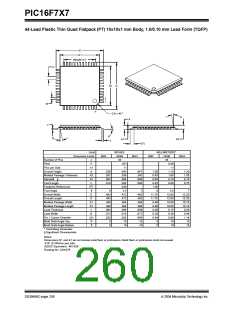
PIC16F7X7
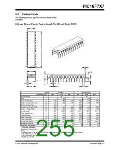
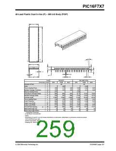
40-Lead Plastic Dual In-line (P) – 600 mil Body (PDIP)
E1
D
2
α
n
1
E
A2
L
A
c
B1
B
β
A1
p
eB
Units
INCHES*
NOM
40
MILLIMETERS
NOM
40
2.54
Dimension Limits
MIN
MAX
MIN
MAX
n
p
Number of Pins
Pitch
.100
Top to Seating Plane
A
.160
.175
.190
.160
4.06
4.45
3.81
4.83
Molded Package Thickness
Base to Seating Plane
Shoulder to Shoulder Width
Molded Package Width
Overall Length
A2
A1
E
.140
.015
.595
.530
2.045
.120
.008
.030
.014
.620
5
.150
3.56
0.38
15.11
13.46
51.94
3.05
0.20
0.76
0.36
15.75
5
4.06
.600
.545
2.058
.130
.012
.050
.018
.650
10
.625
.560
2.065
.135
.015
.070
.022
.680
15
15.24
13.84
52.26
3.30
0.29
1.27
0.46
16.51
10
15.88
14.22
52.45
3.43
0.38
1.78
0.56
17.27
15
E1
D
Tip to Seating Plane
Lead Thickness
L
c
Upper Lead Width
B1
B
Lower Lead Width
Overall Row Spacing
Mold Draft Angle Top
§
eB
α
β
Mold Draft Angle Bottom
* Controlling Parameter
§ Significant Characteristic
5
10
15
5
10
15
Notes:
Dimensions D and E1 do not include mold flash or protrusions. Mold flash or protrusions shall not exceed
.010” (0.254mm) per side.
JEDEC Equivalent: MO-011
Drawing No. C04-016
2004 Microchip Technology Inc.
DS30498C-page 257

 MICROCHIP [ MICROCHIP ]