PIC16F872
Brown-out Reset (BOR). They are not affected by a
WDT Wake-up, which is viewed as the resumption of
normal operation. The TO and PD bits are set or
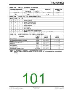
cleared differently in different reset situations as indi-
cated in Table 11-4. These bits are used in software to
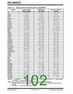
determine the nature of the reset. See Table 11-6 for a
full description of reset states of all registers.
11.3
Reset
The PIC16F872 differentiates between various kinds of
reset:
• Power-on Reset (POR)
• MCLR Reset during normal operation
• MCLR Reset during SLEEP
• WDT Reset (during normal operation)
• WDT Wake-up (during SLEEP)
• Brown-out Reset (BOR)
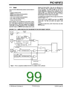
A simplified block diagram of the on-chip reset circuit is
shown in Figure 11-4.
These devices have a MCLR noise filter in the MCLR
Reset path. The filter will detect and ignore small
pulses.
Some registers are not affected in any RESET condi-
tion. Their status is unknown on POR and unchanged
in any other RESET. Most other registers are reset to a
“reset state” on Power-on Reset (POR), on the MCLR
and WDT Reset, on MCLR Reset during SLEEP, and
It should be noted that a WDT Reset does not drive
MCLR pin low.
FIGURE 11-4: SIMPLIFIED BLOCK DIAGRAM OF ON-CHIP RESET CIRCUIT
External
Reset
MCLR
SLEEP
WDT
WDT
Module
Time-out
Reset
VDD rise
detect
Power-on Reset
VDD
Brown-out
Reset
S
R
BODEN
OST/PWRT
OST
Chip_Reset
Q
10-bit Ripple counter
OSC1
(1)
On-chip
RC OSC
PWRT
10-bit Ripple counter
Enable PWRT
Enable OST
Note 1: This is a separate oscillator from the RC oscillator of the CLKIN pin.
1999 Microchip Technology Inc.
Preliminary
DS30221A-page 99

 MICROCHIP [ MICROCHIP ]