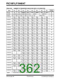
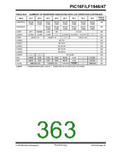
PIC16F/LF1946/47
26.12 Configuring the LCD Module
26.14 LCD Current Consumption
The following is the sequence of steps to configure the
LCD module.
When using the LCD module the current consumption
consists of the following three factors:
1. Select the frame clock prescale using bits
LP<3:0> of the LCDPS register.
• Oscillator Selection
• LCD Bias Source
2. Configure the appropriate pins to function as
segment drivers using the LCDSEn registers.
• Capacitance of the LCD segments
The current consumption of just the LCD module can
be considered negligible compared to these other
factors.
3. Configure the LCD module for the following
using the LCDCON register:
- Multiplex and Bias mode, bits LMUX<1:0>
- Timing source, bits CS<1:0>
- Sleep mode, bit SLPEN
26.14.1 OSCILLATOR SELECTION
The current consumed by the clock source selected
must be considered when using the LCD module. See
Section 29.0 “Electrical Specifications” for oscillator
current consumption information.
4. Write initial values to pixel data registers,
LCDDATA0 through LCDDATA23.
5. Clear LCD Interrupt Flag, LCDIF bit of the PIR2
register and if desired, enable the interrupt by
setting bit LCDIE of the PIE2 register.
26.14.2 LCD BIAS SOURCE
The LCD bias source, internal or external, can contrib-
ute significantly to the current consumption. Use the
highest possible resistor values while maintaining
contrast to minimize current.
6. Configure bias voltages by setting the LCDRL,
LCDREF and the associated ANSELx
registers as needed.
7. Enable the LCD module by setting bit LCDEN of
the LCDCON register.
26.14.3 CAPACITANCE OF THE LCD
SEGMENTS
26.13 Disabling the LCD Module
The LCD segments which can be modeled as capaci-
tors which must be both charged and discharged every
frame. The size of the LCD segment and its technology
determines the segment’s capacitance.
To disable the LCD module, write all ‘0’s to the
LCDCON register.
2010 Microchip Technology Inc.
Preliminary
DS41414A-page 359

 MICROCHIP [ MICROCHIP ]