PIC16F/LF1946/47
26.10 LCD Interrupts
The LCD module provides an interrupt in two cases. An
interrupt when the LCD controller goes from active to
inactive controller. An interrupt also provides unframe
boundaries for Type B waveform. The LCD timing gen-
eration provides an interrupt that defines the LCD
frame timing.
26.10.1 LCD INTERRUPT ON MODULE
SHUTDOWN
An LCD interrupt is generated when the module
completes shutting down (LCDA goes from ‘1’ to ‘0’).
26.10.2 LCD FRAME INTERRUPTS
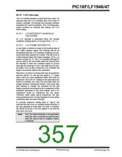
A new frame is defined to begin at the leading edge of
the COM0 common signal. The interrupt will be set
immediately after the LCD controller completes access-
ing all pixel data required for a frame. This will occur at
a fixed interval before the frame boundary (TFINT), as
shown in Figure 26-19. The LCD controller will begin to
access data for the next frame within the interval from
the interrupt to when the controller begins to access
data after the interrupt (TFWR). New data must be writ-
ten within TFWR, as this is when the LCD controller will
begin to access the data for the next frame.
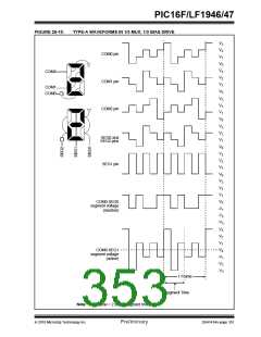
When the LCD driver is running with Type-B waveforms
and the LMUX<1:0> bits are not equal to ‘00’ (static
drive), there are some additional issues that must be
addressed. Since the DC voltage on the pixel takes two
frames to maintain zero volts, the pixel data must not
change between subsequent frames. If the pixel data
were allowed to change, the waveform for the odd
frames would not necessarily be the complement of the
waveform generated in the even frames and a DC
component would be introduced into the panel.
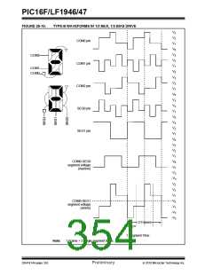
Therefore, when using Type-B waveforms, the user
must synchronize the LCD pixel updates to occur within
a subframe after the frame interrupt.
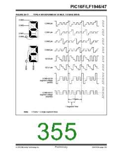
To correctly sequence writing while in Type-B, the
interrupt will only occur on complete phase intervals. If
the user attempts to write when the write is disabled,
the WERR bit of the LCDCON register is set and the
write does not occur.
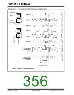
Note: The LCD frame interrupt is not generated
when the Type-A waveform is selected and
when the Type-B with no multiplex (static)
is selected.
2010 Microchip Technology Inc.
Preliminary
DS41414A-page 355

 MICROCHIP [ MICROCHIP ]