PIC16C63A/65B/73B/74B
9.1.2
TIMER1 MODE SELECTION
9.1
Capture Mode
Timer1 must be running in Timer mode or Synchro-
nized Counter mode for the CCP module to use the
capture feature. In Asynchronous Counter mode, the
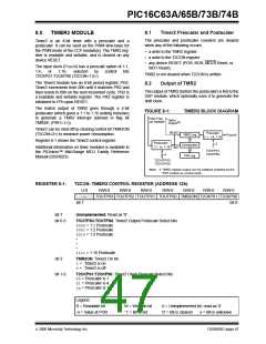
capture operation may not work.
In Capture mode, CCPR1H:CCPR1L captures the
16-bit value of the TMR1 register when an event occurs
on pin RC2/CCP1. An event is defined as one of the fol-
lowing and is configured using CCPxCON<3:0>:
• Every falling edge
• Every rising edge
9.1.3
SOFTWARE INTERRUPT
When the Capture mode is changed, a false capture
interrupt may be generated. The user should keep bit
CCP1IE (PIE1<2>) clear to avoid false interrupts and
should clear the flag bit CCP1IF following any such
change in operating mode.
• Every 4th rising edge
• Every 16th rising edge
An event is selected by control bits CCP1M3:CCP1M0
(CCP1CON<3:0>). When a capture is made, the inter-
rupt request flag bit CCP1IF (PIR1<2>) is set. The
interrupt flag must be cleared in software. If another
capture occurs before the value in register CCPR1 is
read, the previous captured value is overwritten by the
new captured value.
9.1.4
CCP PRESCALER
There are four prescaler settings, specified by bits
CCP1M3:CCP1M0. Whenever the CCP module is
turned off, or the CCP module is not in Capture mode,
the prescaler counter is cleared. Any RESET will clear
the prescaler counter.
9.1.1
CCP PIN CONFIGURATION
In Capture mode, the RC2/CCP1 pin should be config-
ured as an input by setting the TRISC<2> bit.
Switching from one capture prescaler to another may
generate an interrupt. Also, the prescaler counter will
not be cleared, therefore, the first capture may be from
a non-zero prescaler. Example 9-1 shows the recom-
mended method for switching between capture pres-
calers. This example also clears the prescaler counter
and will not generate the “false” interrupt.
Note: If the RC2/CCP1 pin is configured as an
output, a write to the port can cause a
capture condition.
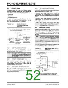
FIGURE 9-1:
CAPTURE MODE
OPERATION BLOCK
DIAGRAM
EXAMPLE 9-1:
CHANGING BETWEEN
CAPTURE PRESCALERS
Set Flag bit CCP1IF
(PIR1<2>)
CLRF
CCP1CON
; Turn CCP module off
Prescaler
÷ 1, 4, 16
MOVLW
NEW_CAPT_PS ; Load the W reg with
; the new prescaler
RC2/CCP1
pin
CCPR1H CCPR1L
; move value and CCP ON
MOVWF
CCP1CON
; Load CCP1CON with this
; value
Capture
Enable
and
Edge Detect
TMR1H
TMR1L
CCP1CON<3:0>
Q’s
2000 Microchip Technology Inc.
DS30605C-page 51

 MICROCHIP [ MICROCHIP ]