PIC12F609/615/12HV609/615
In Compare mode, an event is triggered when the value
CCPR1H:CCPR1L register pair matches the value in
the TMR1H:TMR1L register pair. This event can be a
Special Event Trigger.
6.7
Timer1 Interrupt
The Timer1 register pair (TMR1H:TMR1L) increments
to FFFFh and rolls over to 0000h. When Timer1 rolls
over, the Timer1 interrupt flag bit of the PIR1 register is
set. To enable the interrupt on rollover, you must set
these bits:
For more information, see Section 10.0 “Enhanced
Capture/Compare/PWM (With Auto-Shutdown and
Dead Band) Module (PIC12F615/HV615 only)”.
• Timer1 interrupt enable bit of the PIE1 register
• PEIE bit of the INTCON register
6.10 ECCP Special Event Trigger
(PIC12F615/HV615 only)
• GIE bit of the INTCON register
The interrupt is cleared by clearing the TMR1IF bit in
the Interrupt Service Routine.
If a ECCP is configured to trigger a special event, the
trigger will clear the TMR1H:TMR1L register pair. This
special event does not cause a Timer1 interrupt. The
ECCP module may still be configured to generate a
ECCP interrupt.
Note:
The TMR1H:TTMR1L register pair and the
TMR1IF bit should be cleared before
enabling interrupts.
In this mode of operation, the CCPR1H:CCPR1L regis-
ter pair effectively becomes the period register for
Timer1.
6.8
Timer1 Operation During Sleep
Timer1 can only operate during Sleep when setup in
Asynchronous Counter mode. In this mode, an external
crystal or clock source can be used to increment the
counter. To set up the timer to wake the device:
Timer1 should be synchronized to the FOSC to utilize
the Special Event Trigger. Asynchronous operation of
Timer1 can cause a Special Event Trigger to be
missed.
• TMR1ON bit of the T1CON register must be set
• TMR1IE bit of the PIE1 register must be set
• PEIE bit of the INTCON register must be set
In the event that a write to TMR1H or TMR1L coincides
with a Special Event Trigger from the ECCP, the write
will take precedence.
The device will wake-up on an overflow and execute
the next instruction. If the GIE bit of the INTCON
register is set, the device will call the Interrupt Service
Routine (0004h).
For more information, see Section 10.0 “Enhanced
Capture/Compare/PWM (With Auto-Shutdown and
Dead Band) Module (PIC12F615/HV615 only)”.
6.11 Comparator Synchronization
6.9
ECCP Capture/Compare Time
Base (PIC12F615/HV615 only)
The same clock used to increment Timer1 can also be
used to synchronize the comparator output. This
feature is enabled in the Comparator module.
The ECCP module uses the TMR1H:TMR1L register
pair as the time base when operating in Capture or
Compare mode.
When using the comparator for Timer1 gate, the
comparator output should be synchronized to Timer1.
This ensures Timer1 does not miss an increment if the
comparator changes.
In Capture mode, the value in the TMR1H:TMR1L
register pair is copied into the CCPR1H:CCPR1L
register pair on a configured event.
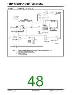
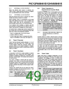
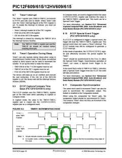
FIGURE 6-2:
TIMER1 INCREMENTING EDGE
T1CKI = 1
when TMR1
Enabled
T1CKI = 0
when TMR1
Enabled
Note 1: Arrows indicate counter increments.
2: In Counter mode, a falling edge must be registered by the counter prior to the first incrementing rising edge of
the clock.
DS41302A-page 48
Preliminary
© 2006 Microchip Technology Inc.

 MICROCHIP [ MICROCHIP ]