MCP23018/MCP23S18
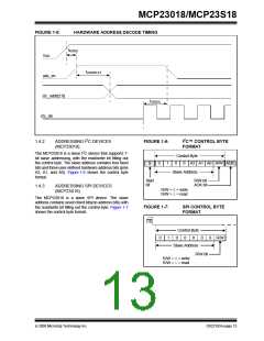
FIGURE 1-5:
HARDWARE ADDRESS DECODE TIMING
tADEN
VDD
tADDRLAT
adc_en
i2c_addr[2:0]
i2c_clk
tADDIS
2
2
1.4.2
ADDRESSING I C DEVICES
(MCP23018)
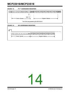
FIGURE 1-6:
I C™ CONTROL BYTE
FORMAT
The MCP23018 is a slave I2C device that supports 7-
bit slave addressing, with the read/write bit filling out
the control byte. The slave address contains four fixed
bits and three user-defined hardware address bits (pins
A2, A1, and A0). Figure 1-6 shows the control byte
format.
Control Byte
A2 A1 A0 R/W ACK
S
0
1
0
0
Slave Address
R/W bit
Start
bit
ACK bit
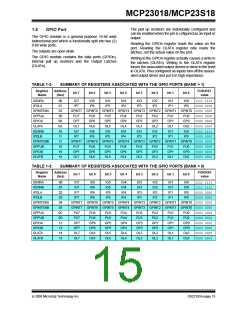
1.4.3
ADDRESSING SPI DEVICES
(MCP23S18)
R/W = 0= write
R/W = 1= read
The MCP23S18 is a slave SPI device. The slave
address contains seven fixed bits(no address bits) with
the read/write bit filling out the control byte. Figure 1-7
shows the control byte format.
FIGURE 1-7:
SPI CONTROL BYTE
FORMAT
CS
Control Byte
0
1
0
0
0
0
0
R/W
Slave Address
R/W bit
R/W = 0= write
R/W = 1= read
© 2008 Microchip Technology Inc.
DS22103A-page 13

 MICROCHIP [ MICROCHIP ]